GaN ePower Integrated Circuits Applied to Motor Drives


The latest ePower™ integrated circuits based on gallium nitride technology by Efficient Power Conversion(EPC)are revolutionizing motor drive applications such as industrial drones, e-bikes, scooters, power tools.
Since its introduction, gallium nitride technology has opened a new era in the world of power electronics. The main differences between gallium nitride and silicon technologies are well described in [1] and are summarized in Table 1.
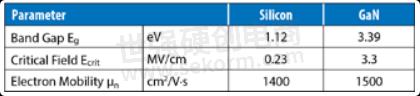
Table 1: Material properties of GaN and Si
The three most important parameters in this comparison are the higher bandgap, critical field, and electron mobility. The critical field, measured in volts per centimeter, determines the threshold for avalanche breakdown. The voltage at which a device breaks down is therefore proportional to the width of the drift region. In the case of GaN, the drift region can be 10 times smaller than in silicon for the same breakdown voltage. When these parameters are all combined, if the critical field of the crystal is 10 times higher, it follows that the electrical terminals can be 10 times closer together. This leads to a clear differentiation factor between GaN and silicon: medium voltage gallium nitride devices can be built on a planar technology while this is cost-prohibitive for silicon devices. To be competitive, silicon devices are made on a vertical technology, usually with gate and source on the top and drain on the bottom, making it physically impossible to have two power devices in the same chip. EPC’s GaN-on-Si planar technology does not have this limit of having to be built vertically, and a schematic cross section of an integrated circuit that takes advantage of this is shown in Figure 1.
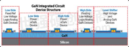
Figure 1: EPC gallium nitride technology enables integration of power devices with gate driver logic
Starting with discrete lateral eGaN® FET devices, EPC quickly moved to higher levels of integration. In 2014, EPC introduced a family of integrated devices comprised of multiple FETs on one chip, which became the starting point for the journey toward a power systemon-a-chip. This trend was expanded with the introduction of the EPC2107 and EPC2108, integrated half bridges with integrated synchronous bootstrap transistors.
In 2018, EPC continued on its integration path with the introduction of GaN ICs combining gate drivers with high-frequency GaN FETs in a single chip for improved efficiency, reduced size, and lower cost. In 2019, the ePower Stage IC family of products redefined power conversion by integrating all requisite power system-on-a-chip functions in a single GaN-on-Si integrated circuit at higher voltages and higher frequency levels - beyond the reach of silicon. Most recently, in 2021 the EPC23101 in combination with the EPC2302 power stage chipset was introduced to the market.
GaN Integrated Circuit Monolithic Power Stage – EPC2152
The first ePower Stage device was introduced in 2019. The EPC2152 is a monolithically integrated single-chip driver plus GaN FET halfbridge power stage IC. Input logic interface, level shifting, bootstrap charging, and gate drive buffer circuits, along with GaN output FETs configured as a half bridge, are integrated within a monolithic chip. This integration resulted in a chip-scale LGA form factor that measures only 3.85 mm x 2.59 mm x 0.63 mm. The two GaN output FETs in half-bridge topology are designed to have the same 8.5 mΩ typical RDS(on).
Integration of GaN FETs with on-chip gate drive buffers practically eliminates the effects of common source inductance and gate drive loop inductance. Power loop inductance is minimized by the LGA pinouts that facilitate the internal vertical layout technique. The block diagram of EPC2152 is shown in Figure 2 and the reference design, EPC9146 BLDC inverter functional block diagram is given in Figure 3.
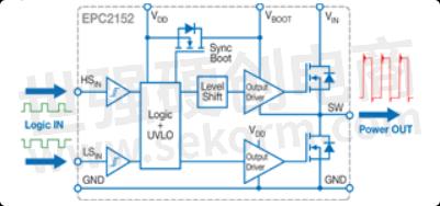
Figure 2: EPC2152 GaN integrated circuit block diagram
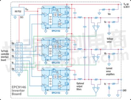
Figure 3: EPC9146 BLDC inverter functional block diagram
EPC9146 motor drive reference design with EPC2152
To demonstrate the capabilities of the EPC2152 integrated circuit in a motor drive inverter, EPC released the EPC9146 reference design. It is a three-phase brushless (BLDC) motor drive inverter board that contains three EPC2152 monolithic ePower stages, 15 Apk (10.5 ARMS) maximum output current. Besides the monolithic power stage, the board contains all the necessary critical functions to support a complete motor drive inverter, including regulated auxiliary power rails for housekeeping supplies, voltage, and temperature sensing, phase current sensing, and protection functions. The various functional blocks of the EPC9146 are shown in Figure 3. This reference design can be used for all applications where the motor phase current is 10 ARMS continuous with 15 ARMS high current operation for a limited time.
GaN IC Power Stage Chipset – EPC23101 in combination with EPC2302
Following the path toward further integration and increased power density, in 2021 EPC introduced a chipset combining the EPC23101, a high-side GaN with a monolithically integrated Half-bridge gate driver, and the EPC2302 GaN FET, as depicted in Figure 4.
The EPC23101 is a 100 V rated monolithic component that integrates input logic interface, level shifting, bootstrap charging, and gate drive buffer circuits, along with a high-side, 2.6 mΩ typical RDS(on) GaN output FET. The EPC2302 is the 100 V companion lowside, 1.4 mΩ typical RDS(on) GaN FET. Over-voltage spikes can be controlled to less than +10 V above the rail and –10 V below ground during hard switching transitions by choosing the tuning resistors, RBOOT and RDRV.
The EPC23101 IC requires only an external 5 V (VDRV) power supply. Internal low-side and high-side power supplies, VDD and VBOOT, are generated from the external supply via a series-connected switch and a synchronous bootstrap switch. The internal circuits can be disabled to reduce quiescent power consumption by connecting the EN pin to VDRV. The FET gate drive voltages are derived from the internal low side and high side power supplies. Full gate drive voltages are only available after the HSIN and LSIN PWM inputs operate for a few cycles. Compared to the EPC2152, the EPC23101 in combination with the EPC2302 allows designers to make higher current inverters.

Figure 4: EPC23101 in combination with EPC2302 GaN IC chipset block diagram
EPC9173 motor drive reference design with EPC23101
To demonstrate the capabilities of the EPC23101 IC in a motor drive inverter, EPC released the EPC9173 reference design. On this board, each half bridge of the three-phase inverter comprises two EPC23101 ICs with their PWM signals cross-connected allowing the insertion of a source shunt to read the current, and shown in Figure 5, with a portion of the schematic.
By using the same IC for the low-side switch, it is possible to have a balanced half-bridge inverter and both switches can float with respect to the Power Ground. This makes the insertion of the source shunt easier, avoiding ground bouncing on the input PWM signal nodes. The EPC9173 board includes an over-current detection circuit that can be used either as an over-current or as a current-limit function, depending on the desired algorithm and modulation.

Figure 5: EPC9173 BLDC inverter functional block diagram
Applications
PWM frequency increase and dead time reduction
GaN integrated circuits and FETs bring several advantages in motor drive applications. The easiest advantage to understand is the reduction of inverter size, which is due to an intrinsic smaller dimension of a GaN FET and ICs versus the equivalent MOSFET. However, to get the most out of the new technology, it is better to operate a motor at a higher PWM frequency and to consequently reduce the dead time [2].
Conventional silicon MOSFET inverters are constrained by high switching losses and by the commutation behavior, and usually are not operated above 40 kHz PWM frequency and with dead time lower than 200 ns. GaN-based inverters are not limited in this sense and can increase the efficiency of the motor because of lower ohmic dissipation due to reduced current ripple (Figure 6, [4]) and fewer torque harmonics that are responsible for motor vibrations [2].

Figure 6: Comparison between measured and estimated PWM-induced losses in a motor with 50% duty cycle square wave voltage excitation [4]
Moreover, increasing switching frequency helps to reduce the input filter and to remove the need for electrolytic capacitors. A comparison between two inverters, one running at 20 kHz, 500 ns dead time, and the other, based on GaN, running at 100 kHz, 14 ns dead time is shown in Table 2. The GaN inverter has no input inductor and uses only two ceramic capacitors. Both inverters were operating in the same setup in the same conditions, and the motor is more efficient because many energy wasting harmonics were removed in the GaN inverter case.
Applications with low L/R time constant in the motor
All applications that require high electrical frequency and fast dynamics, such as drone propellers and e-bike in-pedal motors, use very low inductance (single-digit ΩH range) motors. With the advent of more efficient magnetic circuit designs realized by better materials and higher strength permanent magnets, the number of turns on an electromagnetic phase can be reduced and still produce the same back-emf.
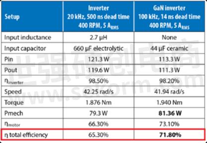
Table 2: Comparison between 20 kHz, 500 ns inverter and 100 kHz, 14 ns GaN inverter with reduced input filter [2]
Permanent magnet brushless motors generate back-emf voltage, e, proportional to speed, ω (e = Ke·ω), and the maximum speed a given motor can run is directly related to the DC bus voltage and the voltage constant, Ke. To increase the speed, it is necessary to lower Ke, by reducing the phase coil turns count, which reduces the inductance by the square of the difference. Limiting the current ripple to less than 10% of the phase current is a good design practice and can be only achieved by increasing the PWM frequency.
The current rise with time is related to the ratio of voltage to inductance, and as inductance decreases, the current rises quicker, as does the PWM induced current ripple. The decreased current rise time and larger ripple increases the amount of heat generated and creates additional EMI noise, which is not desirable. In general, these motors have a small time-constant,
Input current and voltage ripple
The input voltage ripple ∆vin an inverter is proportional to the output phase current and inversely proportional to the PWM frequency and input capacitance, as per eq. (1)

The desired ripple depends on the EMI constraint given by the emissions generated by the cables from the dc source to the inverter. If the PWM frequency is in the range of 20 kHz, the required input capacitance Cin can only be practically obtained by using electrolytic capacitors that are bulky and less reliable than ceramic capacitors. Moreover, the electrolytic capacitors are limited by the RMS current that can flow through them, thus requiring more capacitors in parallel and resulting in a total input capacitance that is higher by more than one order of magnitude than needed for a design. When the frequency is increased to 100 kHz, designers can use ceramic capacitors such as X7R, keeping in mind, as a design rule, the effective capacitance drops to half of the specified value when the applied voltage is half of the rated voltage. The EPC9173 reference design provides for both electrolytic and ceramic capacitors, giving chance for designers to select their preferred switching frequency and to add or remove the capacitors as preferred.
Power tools with trapezoidal modulation
Many power tools applications are still using trapezoidal modulation schemes and related inverter schematics. Usually, these applications are based on three hall sensors to detect the rotor position with a resolution of 60 electrical degrees, and they have a single shunt to measure the current in the DC bus return. The six-step operation has many advantages for BLDC drives, such as maximum power utilization and widened flux-weakening region. However, due to the maximum utilization of inverter output, a saturation of the current regulator makes it difficult to maintain instantaneous current control capability. In most conventional systems it is implemented by voltage angle control with cycle-by-cycle current limit, with unsatisfactory dynamic performance. If the current limit is reached during the PWM cycle, the energizing device (depending on the current direction) is switched off until the next PWM cycle.
The principle of the BLDC motor is to energize the phase pair, which can produce the highest torque. To optimize this effect the back-emf shape is designed to be trapezoidal, but, in reality, it is sinusoidal with some higher harmonics. The combination of a DC current with a trapezoidal back-emf makes it theoretically possible to produce a constant torque. In practice, the current cannot be established instantaneously in a motor phase. As a consequence, the torque ripple is present at each 60-degree phase commutation.
With the current-limiting cycle-by-cycle scheme and low inductance motors, the lower the PWM frequency, the higher the current ripple. This in turn generates heat and unnecessary power dissipation. Using a GaN inverter, with the same trapezoidal scheme, makes it possible to increase the PWM frequency and then reduce the current ripple, obtaining higher efficiency, less heat, and fewer vibrations.
The GaN motor drive reference designs EPC9173 and EPC9167 are equipped with a current comparator circuit whose output can be used by the microcontroller as a signal for cycle-by-cycle current limiting to follow a trapezoidal modulation. With this system, power tools designers can test the reference designs to assess the GaN advantage in their application.
Conclusions
When dealing with motor applications, GaN inverters can increase the efficiency of the system if PWM frequency is increased, the dead time is drastically reduced, and the input capacitance is converted from electrolytic capacitors to ceramic capacitors. Using EPC’s new GaN integrated circuits, such as the EPC2152 and EPC23101, results in increased power density and system efficiency, while saving much system design effort.
- |
- +1 赞 0
- 收藏
- 评论 0
本文由酉水浪子转载自EPC,原文标题为:GaN ePower Integrated Circuits Applied to Motor Drives,本站所有转载文章系出于传递更多信息之目的,且明确注明来源,不希望被转载的媒体或个人可与我们联系,我们将立即进行删除处理。
相关推荐

EPC eGaN®FET/晶体管选型表
EPC提供增强型氮化镓半桥功率晶体管/增强型功率晶体管/功率晶体管的选型:配置:Dual Common Source、Dual with Sync Boot、Half Bridge、Half Bridge Driver IC、HS FET + Driver + Level Shift、Single、Single - AEC Q101、Single – Rad Hard、Single with Gate Diode、Single with Gate Diode – AEC-Q101、Dual Common Source - AEC Q101,VDS最大值(V):15~350V;VGS最大值(V):5.75~7V
|
产品型号
|
品类
|
Configuration
|
VDSmax(V)
|
VGSmax(V)
|
Max RDS(on) (mΩ)
@ 5 VGS
|
QG typ(nC)
|
QGS typ (nC)
|
QGD typ (nC)
|
QOSS typ (nC)
|
QRR(nC)
|
CISS (pF)
|
COSS (pF)
|
CRSS (pF)
|
ID(A)
|
Pulsed ID (A)
|
Max TJ (°C)
|
Package(mm)
|
Launch Date
|
|
EPC2040
|
Enhancement Mode Power Transistor
|
Single
|
15
|
6
|
30
|
0.745
|
0.23
|
0.14
|
0.42
|
0
|
86
|
67
|
20
|
3.4
|
28
|
150
|
BGA 0.85 x 1.2
|
Apr, 2017
|

EPC氮化镓®FET EPC2302鉴定报告
本报告总结了EPC2302产品的认证测试结果,该产品是一款100V eGaN功率晶体管,采用QFN封装。测试包括高温反向偏置(HTRB)、高温栅极偏置(HTGB)、高温存储(HTS)、湿度敏感度等级(MSL)、无偏压高度加速应力测试(uHAST)等多种环境下的可靠性测试。所有测试均符合或超过了规定的标准,EPC2302已通过认证并可用于生产。
EPC - 氮化镓®场效应晶体管,EGAN® FET,EPC2302

eGaN® FET DATASHEET EPC2366
EPC2366是一款增强型功率晶体管,专为DC-DC转换中的关键应用设计。该器件具有极高的电子迁移率和低温度系数,导致非常低的RDS(on)值。其横向结构提供了非常低的栅极电荷(QG)和极快的开关时间。这些特性使得电源转换器开关频率更快,从而实现更高的功率密度、更高的效率和更紧凑的封装。
EPC - EGAN®功率开关HEMT,EPC2366,同步整流器,DC-DC转换
EPC2252氮化镓®FET规格书
本资料介绍了EPC2252增强型功率晶体管,一款基于氮化镓(GaN)技术的器件。该产品具有低导通电阻、高开关频率和高效能的特点,适用于汽车激光雷达/TOF、服务器、脉冲电源、隔离电源、点负载转换器、音频放大器和LED照明等领域。
EPC - 氮化镓®场效应晶体管,ENHANCEMENT MODE POWER TRANSISTOR,EGAN® FET,增强型功率晶体管,EPC2252,48 V SERVERS,CLASS D AUDIO,ISOLATED POWER SUPPLIES,汽车激光雷达,隔离电源,LED LIGHTING,LOW INDUCTANCE MOTOR DRIVE,负载点转换器,AUTOMOTIVE LIDAR,PULSED POWER,LED照明,低电感电机驱动,D类音频,48 V服务器,POINT OF LOAD CONVERTERS,脉冲功率,AUTOMOTIVE TOF,汽车TOF
EPC23101-ePower™Stage IC氮化镓®FET规格书
该资料介绍了EPC23101 ePowerTM Stage集成电路,这是一种集成了高侧eGaN® FET、内部栅极驱动器和电平转换器的高效功率转换解决方案。该芯片适用于多种转换器拓扑,如降压、升压和升降压转换器,以及半桥、全桥LLC转换器和电机驱动逆变器。它具有低导通电阻、高开关频率和低静态电流等特点,适用于高效率、小型化和易于制造的电源设计。
EPC - 氮化镓®场效应晶体管,EGAN® FET,EPOWER™ STAGE IC,EPOWER™阶段IC,EPC23101,MOTOR DRIVE INVERTER,BUCK CONVERTERS,全桥变换器,FULL BRIDGE CONVERTERS,LLC转换器,LLC CONVERTERS,半桥变换器,BOOST CONVERTERS,电机驱动逆变器,降压-升压转换器,升压变换器,巴克变换器,HALF-BRIDGE CONVERTERS,D类音频放大器,CLASS D AUDIO AMPLIFIER,BUCK-BOOST CONVERTERS
eGaN® FET DATASHEET EPC2204A
本资料详细介绍了EPC2204A eGaN® FET的电气特性和热特性。资料涵盖了静态和动态电气参数,包括漏电流、导通电阻、栅极电荷等,以及热阻和热响应曲线。此外,还提供了推荐的土地图案和印刷电路板(PCB)设计信息。
EPC - 氮化镓®场效应晶体管,EGAN® FET,EPC2204A,EMOBILITY,情绪化

How2GaN | 如何设计具有最佳布局的eGaN® FET功率级
eGaN FET的开关速度比硅基MOSFET更快,因此需要更仔细地考虑印刷电路板(PCB)布局设计以最小化寄生电感。寄生电感会导致过冲电压更高,同时减慢开关速度。本篇笔记将会探讨使用eGaN FET设计最佳功率级布局的关键步骤,来避免上述不良影响并最大化转换器性能。
EPC2901C_55–增强型功率晶体管eGallium Nitrium®FET规格书
本资料详细介绍了EPC2901C_55型号的eGaN® FET(增强型场效应晶体管)的特性和应用。该器件采用氮化镓技术,具有低导通电阻、高开关频率和低开关损耗,适用于高频DC-DC转换、工业自动化、同步整流和低电感电机驱动等领域。
EPC - 氮化镓®场效应晶体管,ENHANCEMENT MODE POWER TRANSISTOR,EGAN® FET,增强型功率晶体管,EPC2901C_55,LOW INDUCTANCE MOTOR DRIVES,INDUSTRIAL AUTOMATION,工业自动化,高频DC-DC变换,HIGH-FREQUENCY DC-DC CONVERSION,低电感电机驱动
eGaN® FET DATASHEET EPC2202
该资料详细介绍了EPC2202 eGaN® FET的特性和应用。资料涵盖了静态和动态特性、热特性、电容特性、封装信息以及组装建议,旨在为工程师提供全面的产品信息。
EPC - 氮化镓®场效应晶体管,EGAN® FET,EPC2202,工业控制等,高效率电源转换,汽车电子

EPC Announces a New 3-phase BLDC Motor Drive Inverter Using the EPC2065 EGaN® FET
EPC announces the availability of the EPC9167, a 3-phase BLDC motor drive inverter using the EPC2065 eGaN® FET.
EPC2619–增强型功率晶体管eGallium Nitrium®FET规格书
本资料介绍了EPC2619增强型功率晶体管,一款基于氮化镓(Gallium Nitride)技术的器件。该晶体管具有极低的导通电阻RDS(on)、高电子迁移率和低温度系数,适用于高频开关应用,同时提供优异的热性能和效率。
EPC - 氮化镓®场效应晶体管,ENHANCEMENT MODE POWER TRANSISTOR,EGAN® FET,增强型功率晶体管,EPC2619,DC-DC CONVERTERS,CLASS D AUDIO,机器人,MOTOR DRIVE,负载点转换器,电动机驱动,电动工具,USB PD 3.1充电器,埃斯科特斯,POINT OF LOAD CONVERTERS,MEDICAL ROBOTS,直流伺服,稳定器,DC-DC转换器,ROBOTS,EBIKES,ESCOOTERS,USB PD 3.1 CHARGERS,BATTERY CHARGERS,ISOLATED DC-DC CONVERTERS,POWER TOOLS,D类音频,医疗机器人,太阳能优化器,STORAGE,SOLAR OPTIMIZERS,DC SERVO,埃比克斯,STABILIZERS,存储器,蓄电池充电器,隔离DC-DC转换器
eGaN® FET DATASHEET EPC29215_55
本资料详细介绍了EPC29215_55型号的eGaN® FET(氮化镓场效应晶体管)的特性。该器件具有低导通电阻、高开关频率和低开关损耗,适用于DC-DC转换器、BLDC电机驱动、同步整流、多级AC-DC电源、无线充电、太阳能微型逆变器、机器人和Class-D音频等领域。
EPC - 氮化镓®场效应晶体管,EGAN® FET,EPC29215_55,D类音频,机器人,无线电源,AC/DC和DC-DC同步整流,多级AC/DC电源,DC-DC转换器,BLDC电机驱动,太阳能微型逆变器

面向直流无刷(BLDC)电机的 eGaN® FET 及集成电路
本文介绍了eGaN®技术在直流无刷电机(BLDC)应用中的优势,尤其是在工业自动化、汽车制造和医疗设备领域的应用。eGaN® FET相比传统硅基MOSFET具有更高的开关速度、更低的开关损耗和更小的尺寸,适用于线性电机、伺服电机、机器人驱动器等。文章还提供了EPC公司生产的eGaN® FET器件型号配置和典型值参数。
EPC - 开发板,氮化镓®场效应晶体管,EGAN FET,EGAN® FET,演示板,集成电路,氮化镓场效应晶体管,EPC2012C,EPC2215,EPC9049,EPC2052,EPC2051,EPC2054,EPC2055,EPC9087,EPC9040,EPC2102,EPC2104,EPC2302,EPC2103,EPC2106,EPC2304,EPC2306,EPC2305,EPC2065,EPC90151,EPC9057,EPC90152,EPC2067,EPC2066,EPC90150,EPC9097,EPC90145,EPC90142,EPC9055,EPC90143,EPC9099,EPC9092,EPC90148,EPC90149,EPC9050,EPC90146,EPC9094,EPC90147,EPC9091,EPC2036,EPC2035,EPC2038,EPC2037,EPC2014C,EPC2039,EPC9507,EPC2071,EPC23101,EPC23102,EPC23103,EPC90140,EPC23104,EPC2031,EPC2152,EPC90132,EPC90137,EPC90138,EPC9061,EPC2308,EPC2307,EPC9005C,EPC9004C,EPC2204,EPC2206,EPC9038,EPC9039,EPC2040,EPC2044,EPC2088,EPC90122,EPC90123,EPC90120,EPC90128,SEAT COOLING FAN MOTOR,电子辅助转向系统,自动舱门开/关电机,汽车制造,AUTOMATIC HATCH OPEN/CLOSE MOTOR,EPS,座椅冷却风扇电机,FEED DRIVE,ELECTRONIC POWER STEERING MOTOR,机械人,手术机械人,DOOR LOCK MOTOR,门锁电机,工厂传送带,DOOR OPEN/CLOSE MOTOR,电动油泵,门开/关电机,ELECTRIC ACTIVE STABILIZER MOTOR,直流无刷电机,汽车应用,HEADLIGHT OPTICAL AXIS DRIVE MOTOR,CNC机械工具,进给传动,伺服电机,直流无刷(BLDC)电机,大灯光轴驱动电机,医护手术机械人,电动驻车制动电机,工业自动化,电动主动稳定器电机,进给驱动器,工业应用,ELECTRIC PARKING BRAKE MOTOR,线性电机,挤压机驱动电机,工业机械人,ELECTRIC OIL PUMP,电子助力转向马达


EPC2121–双向镓氮®功率开关镓氮®FET规格书
本资料为EPC2121双向eGaN®功率开关的数据表,介绍了该器件的性能参数、特性及应用。EPC2121采用氮化镓技术,具有低导通电阻、高频率切换能力等特点,适用于多种电源转换应用。
EPC - BIDIRECTIONAL EGAN® POWER SWITCH,氮化镓®场效应晶体管,EGAN® FET,双向氮化镓®电源开关,EPC2121,SOLID-STATE RELAY,温控器,THERMOSTAT,BATTERY PROTECTION,固态继电器,REVERSE BATTERY PROTECTION,电池保护,USB PD 3.1 PORT PROTECTION,反向电池保护,USB PD 3.1端口保护

EPC氮化镓晶体管选型表
EPC提供以下氮化镓功率晶体管/GaN功率晶体管选型,最大耐压15V-350V,持续电流0.5A-90A,导通阻抗1.45Ω-3300mΩ,导通电荷0.044nC-19nC,峰值电流0.5A-590A。
|
产品型号
|
品类
|
最大耐压(V)
|
持续电流(A)
|
导通阻抗(mΩ)
|
导通电荷(nC)
|
峰值电流(A)
|
封装(mm)
|
|
EPC2040
|
Enhancement Mode Power Transistor
|
15V
|
3.4A
|
30mΩ
|
0.745nC
|
28A
|
BGA 0.85 mm*1.2mm
|

电子商城
品牌:EPC
品类:Enhancement-Mode GaN Power Transistor Half Bridge
价格:¥6.7699
现货: 2,417
品牌:EPC
品类:Enhancement-Mode GaN Power Transistor Half Bridge
价格:¥6.2849
现货: 2,356


授权代理品牌:集成电路


授权代理品牌:分立元件


授权代理品牌:接插件及结构件


授权代理品牌:部件、组件及配件


授权代理品牌:电源及模块


授权代理品牌:电子材料


授权代理品牌:仪器仪表及测试配组件


授权代理品牌:电工工具及材料


授权代理品牌:机械电子元件


授权代理品牌:加工与定制


登录 | 立即注册
提交评论