Rogers developed Thermal Simulation Tools to Accelerate Time to Market


When using SiC, a key aspect to consider is how to dissipate the losses from a smaller area compared to that of Si devices. The higher cost of these devices is pushing many to reduce the die size to a minimum, further enhancing the challenge of dissipating the losses without increasing the total system costs.
Multiple recent power module concepts have been released to address this challenge; one thing most of them have in common is their utilization of metalized ceramic substrates. Their superior mechanical, thermal, and electrical characteristics make them an essential element in the design of power modules for EV traction applications. It is important to pay special attention when selecting the substrate's material combination to achieve the best thermal performance, meet reliability requirements and optimize costs.
The questions arise — what is the best material combination, and should an HPS (Zr doped Al2O3) substrate with 0.3 mm Cu be selected? On the one hand, there can be good mechanical stability at a great cost, yet have limited thermal performance. Or, what if the Cu thickness is increased to 0.6 mm? Also, what if the substrate is changed to Si3N4, increasing the cost but also the thermal performance?
There are no simple answers to the "what if" questions.
To help customers answer these questions and accelerate their decisions, the team at ROGERS developed a series of simulation tools using our extensive experience. In this blog, we will showcase a small portion of these simulation tools using a simplified thermal model. This simulation could be extended to include customized layouts, different module constructions (e.g., baseplate with or without fins; dual-side cooling; etc.), or other material combinations to analyze impacts on a specific design in more detail. Additionally, it is possible to run a more in-depth fluid analysis using the FEM simulation, as well as lifetime prediction models.
The model
To keep things simple for the purpose of this blog, we used a basic generic model, based on a classic baseless module connected to a copper water cooler at a constant temperature (see Figure 1). The module is either soldered to the heat sink or connected to a thermal interface material (TIM). We compared substrate materials and Cu thicknesses (see Table 1) on two different layouts. The first layout has enough Cu area around the dice to enable a good thermal spreading (see Figure 2). On the second layout, the dice are as close as possible and have a minimal Cu area around them (see Figure 3). In order to further simplify the model, we considered a single heat transfer coefficient of 15000 W/m2K for the heat sink and a constant loss of 200 W per die.
The model could be made significantly more complex. Customized layouts, dynamic losses, specific heat sink profiles, or interconnection technologies are among the parameters that could be adapted to a specific request.
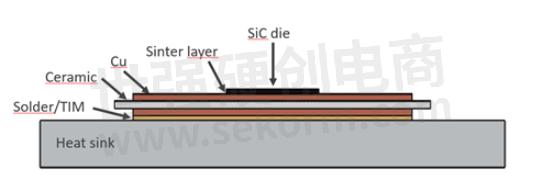
Figure 1: cross-section simplified model
Table 1: Materials and properties used for the simulation
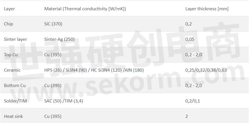
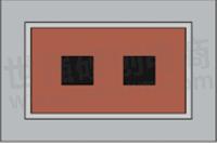
Figure 2: Layout 1; 5x5mm SiC dice with 5mm free Cu around them
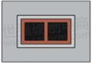
Figure 3: Layout 2; 5x5 SiC dice with 1mm free Cu around them
Analyzing some scenarios
With the model built, we can look at several possible scenarios. We could analyze several different influencing parameters, such as the ceramic material, its thickness, the Cu thickness, the influence of the interconnection to the heat sink (TIM or solder/sinter), the distance between chips, and many more. In order to keep it simple, we concentrated on just a couple of scenarios, but nevertheless, a more in-depth analysis could be conducted upon request.
We know that some of the temperatures presented in the figures below are well beyond any design targets. They are not meant to be taken literally, but rather as an indication to compare different solutions. Another approach to this would have been to normalize the results.
The influence of the ceramic substrate and the layout
In the first stage, we will compare the influence of the ceramic substrate material with the two different layouts on the chip temperature. In Figure 4, the comparison can be observed when using either a solder material to the heat sink or a standard 0.3 mm Cu thickness for all solutions.
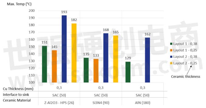
Figure 4: Maximum chip temperature for different ceramic materials and thicknesses with 0.3mm Cu and soldered to the heat sink with a SAC material
The graphic above contains a lot of information, but firstly, we can highlight the significant difference between Layout 1 and 2 regardless of the material combination. This highlights the need to have sufficient Cu area around the dice to facilitate the heat spreading. The influence of the layout could be reduced with a higher heat transfer coefficient to the ambient which would enhance the thermal dissipation in the y-axis. Nevertheless, sufficient Cu area around the dice should be used, if possible.
As expected, using ceramic materials with a higher thermal conductivity results in a lower temperature. For the same material thickness, there is a big step between HPS and the remaining materials. However, the difference between a standard Si3N4 with 90 W/mK and AlN, which has doubled the thermal conductivity, is still visible but less pronounced.
We can also observe that material thickness can bring you an extra degree Celsius that it is needed to meet design parameters, which is especially true for HPS.
The influence of the Cu thickness
Unfortunately, an improvement on the ceramic substrate does not come for free and, in some designs, the increase in the ceramic's cost cannot be justified. A more economical alternative would be to increase the thickness of the Cu layer, e.g. from 0.3 to 0.6 or even 2 mm. The latter brings some design and reliability challenges but it is still worth considering. The result of the comparison of the different Cu thicknesses can be seen in Figures 5 and 6 with layouts 1 and 2 respectively.
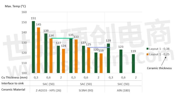
Figure 5: Maximum chip temperature for different ceramic and Cu thicknesses, soldered to the heat sink with a SAC material. Only for Layout 1
In Figure 5, we can clearly observe that when enough Cu is around the dice, increasing the thickness of this layer can bring a tremendous benefit to the system. For instance, a 0.6mm Cu layer used with a 0.25 mm HPS can achieve a similar chip temperature as a 0.3 mm Cu Si3N4 at a better cost (green line). Moreover, a 0.6 mm Cu Si3N4 could also improve the performance compared to a 0.3 mm Cu AlN with better reliability.
An even thicker Cu layer of 2mm brings yet an additional improvement in the chip temperature. At this point, we can see a certain saturation in the improvement, and thicker Cu would not bring any significant benefit.
Of course, it is not always possible to place the dice with enough Cu area around them. In case the layout is more compact, the situation changes completely as can be observed in Figure 6.
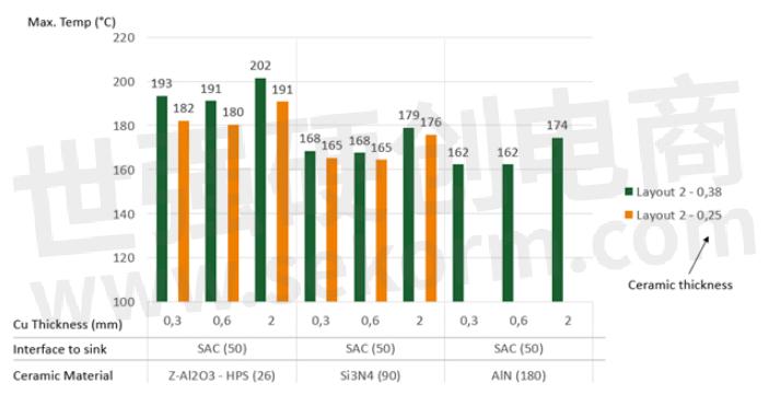
Figure 6: Maximum chip temperature for different ceramic and Cu thicknesses, soldered to the heat sink with a SAC material. Only for Layout 2
In this case, the thicker Cu does not bring any added value, as the dice do not benefit from the spreading effect of the thicker Cu. Moreover, for very thick Cu layers, such as 2mm, the added material hinders the thermal conduction in the y-axis, reducing the Rth and thus increasing the chip temperature. Overall, thicker Cu might be an advantage under certain conditions, but it is not always the best solution.
The influence of the interface to the heat sink
So far, we have focused on the substrates. There are of course many other barriers in the thermal path, with the interface to the heat sink being one of the most relevant. In Figure 7 we can see the results of this comparison.
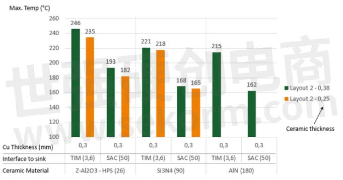
Figure 7: Maximum chip temperature for different ceramics, soldered to the heat sink with a SAC material or connected with a standard TIM. Only for Layout 2
Regardless of which ceramic substrate is used, the temperature differences are quite striking. The temperatures are in both cases out of most design targets; nevertheless, it shows the relevance of this interface layer in the overall design. One could argue that the thickness for the TIM layer (100 µm) and the material itself could be further optimized, but so could the solder material.
Conclusion
Deciding on the best set of materials for your power module can be a laborious task. Many different parameters must be considered to find the best solution, such as the ceramic material, its thickness, the thickness of the Cu, the interface to the heat sink, the cooling method, and so on. Doing this by trial-and-error testing is impractical, and the support of simulation tools is necessary to ensure adequate time-to-market and development costs.
At Rogers, we have developed a series of tools to help our customers and support their decision-making. In this blog, we have shown a small part of these tools with a simple thermal model. Other aspects, such as reliability and cost, can also be simulated to complete the picture. Furthermore, the thermal model can be adapted to more complex and real environments. We are committed to extending and improving these tools and using them to the service of customers to help reduce their design costs and to save time.
Do you have any questions or require more information about Rogers' ceramic substrates?
- |
- +1 赞 0
- 收藏
- 评论 0
本文由翊翊所思转载自Rogers,原文标题为:Accelerating Time to Market with Thermal Simulation Tools,本站所有转载文章系出于传递更多信息之目的,且明确注明来源,不希望被转载的媒体或个人可与我们联系,我们将立即进行删除处理。
相关推荐

Rogers高频板RO4350B板材在24GHz时介电常数和损耗因子
Rogers高频板RO4350B达到了成本和高频性能的最优化,是最具性价比的低损耗高频板材。为了更好的实现设计要求,笔者在设计微带阵列天线时研究了基于Rogers高频板RO4350B板材的微带传输线在24GHz的插入损耗。

Littelfuse(力特)IXYS功率半导体选型指南
Introduction of Littelfuse Index Symbols and Terms/Nomenclature New Pressfit Pin packages ISOPLUS™ family IGBT Discretes IGBT Modules Power MOSFETs Diodes Thyristors Rectifier Bridges Protection Devices Gate Drivers/Power Relays Diode & Thyristor(IXYS Chippenham) Power Semiconductor Chips/Direct Copper Bonded Ceramic Substrates Application Notes Highlights Outline Drawings
LITTELFUSE - 压装式IGBT,制动整流器总成,外围组件,BIMOSFETS,SIX PHASE THYRISTOR,晶闸管,功率金氧半电晶体,OPTICALLY ISOLATED PHOTOVOLTAIC GATE DRIVERS,WATER COOLED DUAL DIODE MODULES,快速恢复外延二极管,快速恢复二极管,快速关断晶闸管,RECTIFIERS,相位支路/CBI模块,HALF BRIDGE MODULES IN 34/62MM HOUSINGS,SILICONCARBIDE POWER MOSFETS,FAST PHASE CONTROL THYRISTORS,SOFT RECOVERY DIODES,保护装置,MOSFET MODULES,THYRISTOR,快恢复二极管二极管,BOX CLAMPS,功率半导体组件,不对称和脉冲晶闸管,OPTICALLY ISOLATED AC POWER SWITCHES,单晶闸管模块,THREE PHASE FULLY CONTROLLED BRIDGES,BRAKE IGBT MODULES,整流器,RESETTABLE PTCS,LINEAR L2™ POWER MOSFETS,整流桥,超快恢复二极管,半快二极管,散热器,IGBT MODULES,SINGLE PHASE FULLY CONTROLLED BRIDGES,TRIAC,高频场效应晶体管,ULTRA JUNCTION POWER MOSFETS,TRIODE-REVERSE CONDUCTING THYRISTOR,超结功率MOSFET,DUAL ULTRAFAST DIODES,WATER COOLED DUAL THYRISTOR MODULES,肖特基,FRED,BRAKING RECTIFIER ASSEMBLIES,MOSFET模块,快速导通二极管(BOD),TRENCH POWER MOSFETS,POLAR™MOSFET,AC CONTROLLER,SINGLE PHASE DIODE BRIDGES,FAST BODY DIODE,冷却器,BAR CLAMPS,升压模块,BRAKE/BUCK/BOOST CHOPPER IGBT MODULES,IGBT HALF BRIDGE MODULES,POWER SEMICONDUCTOR ASSEMBLIES,SIC MOSFETS,传统MOSFET,POWER SEMICONDUCTOR CHIPS,带制动装置的整流桥,IGNITION IGBTS,POWER MOSFETS,离散相控晶闸管,门驱动器,PHASE CONTROL THYRISTORS,OPTICALLY ISOLATED LOAD-BIASED GATE DRIVERS,RECTIFIER DIODE,THYRISTORS,HIPERFRED™ DIODES,LEGACY MOSFETS,HIGH POWER SONIC FRD,HIPERFRED ™ 二极管,SOFT RECOVERY DIODE,PULSE THYRISTORS,HIGH SPEED DIGITAL OPTICAL ISOLATORS,HIPERFETS,分布式门极晶闸管,WATER COOLED DIODE MODULES,声波-FRD™ 二极管,IGBTS,COOLERS,DISTRIBUTED GATE THYRISTORS,棒夹,DEPLETION-MODE MOSFETS,沟道MOSFETS,功率半导体附件,SILICON CARBIDE SCHOTTKY DIODES,SONIC-FRD™ DIODES,BOOST MODULES,DIODE MODULES,MEDIUM VOLTAGE THYRISTORS,SINGLE DIODE MODULES,STANDARD MOSFETS,软恢复二极管,快恢复二极管,全桥和制动/降压/增压模块,P沟道MOSFET,快速二极管整流桥,LINEAR OPTOCOUPLERS,SIC DIODES,HIPERFRED2™ DIODES,PLANAR IGBTS,RECTIFIER BRIDGES,相控晶闸管,PHASE LEG IGBT MODULE,MOSFETS,HIPERFETS (FBD),晶闸管模块,中压晶闸管,DUAL DIODE MODULES,DUAL THYRISTOR,整流二极管,TRIACS,IGBT GATE DRIVER,SIC SCHOTTKY DIODES,MISCELLANEOUS RELAYS,P-CHANNEL MOSFETS,GATE TURN OFF THYRISTORS,单二极管模块,肖特基GEN2二极管,AC REGULATORS,快体二极管,BREAK-OVER DIODES,标准底座夹具套件,WATER COOLED DIODE,SUPERJUNCTION POWER MOSFET,MOSFETS器件,OPTICALLY ISOLATED I2C BUS REPEATERS,导通二极管(BOD),Q3-CLASS HIPERFET,HEATSINKS,DIRECT COPPER BONDED CERAMIC SUBSTRATES,SINGLE THYRISTOR MODULES,AVALANCHE DIODES,二极管,N-CHANNEL DEPLETION MODE FETS,34/62MM外壳中的半桥模块,FUSES,FAST BREAK-OVER DIODES,线性L2™ 功率金氧半电晶体,SEMIFAST DIODES,MODULES,POLAR™ MOSFETS,HIGH VOLTAGE RECTIFIER MODULES,LEGACY POWER MOSFETS,LOW ON-STATE VOLTAGE NPT IGBTS,HIGH VOLTAGE NPT IGBTS,FAST RECOVERY DIODE,DUAL SPEED DIGITAL OPTICAL ISOLATOR,RECTIFIER BRIDGES WITH FAST DIODES,HIPERFRED2型™ 二极管,PRESS-PACK IGBT,TRENCH IGBTS,POWER RELAYS,RECTIFIER DIODE MODULES,6-PACK MODULES,功率因数校正模块,FULL BRIDGE AND BRAKE / BUCK / BOOST MODULES,SIC MOSFET,点火IGBTS,箱形夹具,RECTIFIER DIODES,HIPERDYN™ FREDS,EXTRA FAST RECOVERY DIODES,LOW-SIDE GATE DRIVERS,整流二极管模块,配件,VERY HIGH VOLTAGE POWER MOSFETS,WATER COOLED THYRISTOR MODULES,双极场效应晶体管,PROTECTION DEVICES,HIPERFET(FBD),HALF BRIDGE MODULES,HALF CONTROLLED RECTIFIER BRIDGES,绝缘栅双极晶体管,DIODES,PHASE LEG / CBI MODULES,SIX-PACK TRENCH MOSFET,HIPERDYN™FREDS,THREE PHASE DIODE BRIDGE,BUCK IGBT MODULES,DUAL THYRISTOR MODULES,FAST TURN OFF THYRISTORS,POWER SEMICONDUCTOR ACCESSORIES,整流管,半桥模块,功率继电器,ASYMMETRIC THYRISTORS,PRESS-PACK IGBT GATE DRIVE UNITS,DISCRETES PHASE CONTROL THYRISTORS,大功率声波频率分布,SEMIFAST DIODES,FAST RECOVERY DIODES,GTOS,双向可控硅,FAULT PROTECTED RELAYS,1-FORM-A RELAYS,1-FORM-B RELAYS,CBI 3 IGBT MODULES,RECTIFIER BRIDGES WITH BRAKE UNIT,SINGLE-CHANEL EACH DIRECTION DIGITAL OPTICAL ISOLATOR,SIX PHASE DIODE,FRED DIODES,RECTIFIER,FULL BRIDGE IGBT MODULES,BOOST CHOPPER IGBT MODULES,PERIPHERAL COMPONENTS,压装式IGBT门极驱动单元,ASYMMETRIC AND PULSE THYRISTORS,TVS DIODES,SCHOTTKY GEN2 DIODES,NPT IGBT,SIX-PACK IGBT MODULES,HIPERFRED™ 模块,6件装模块,耗尽模式MOSFET,VERY HIGH VOLTAGE NPT IGBTS,交流控制器,HIPERFRED™ MODULES,水冷二极管,CBI 2 IGBT MODULES,PT IGBTS,TRENCH MOSFETS,双超快二极管,ACCESSORIES,Q3级HIPERFET,IGBT,MOS-GATED THYRISTORS,雪崩二极管,THYRISTOR MODULES,BREAK-OVER DIODES (BOD),IGBT模块,REVERSE CONDUCTING IGBTS,SCHOTTKY DIODES,POWER FACTOR CORRECTION MODULES,POWER SEMICONDUCTOR,SIC肖特基二极管,二极管模块,FAST BREAK-OVER DIODES (BOD),SUPERJUNCTION POWER MOSFETS,FAST TURN-OFF THYRISTORS,双二极管模块,SIC GATE DRIVER,STANDARD BASE CLAMP KITS,双晶闸管,SOLID STATE RELAYS,STANDARD BAR CLAMPS,INSULATED GATE BI-POLAR TRANSISTORS,GATE DRIVERS,R1280NC25M,MCD 26-16IO1B,N2055HE420,IXTT 30N50L2,R1280NC25K,R1280NC25L,MCD 56-18IO8B,IXBOD 2-52R,R1280NC25J,IXTQ 52N30P,MCK 200-18IO1,IXYR 100N120C3,LSIC2SD120C05,MDC600-22IO1W,IXYH 16N250CV1HV,LSIC2SD120C08,M0863LC360,IXTP 100N15X4,VBO 125-08NO7,DPG 15I200PA,F1600NC080,IXTH 1N450HV,T0600TB45A,LSIC2SD065E40CCA,DSEP 2X91-03A,IXBOD 2-51R,IXTX 4N300P3HV,IXTA 36N30P,VBO 72-18NO7,M4305TJ240,IXFR 64N60P,N6405EA240,IXYR 50N120C3D1,MCD580-28IO7,VUO 25-14NO8,0440 007.WRA,IXFY 36N20X3,VBO 25-12NO2,IXTT 120N15P,M1010NC400,IXBH 6N170,MCC 56-14IO1,VBE 26-06NO7,MCD160-30IO3,SXB4869G,IXTJ 3N150,DHG 10I1200PM,IXTH 120P065T,VTO 39-08HO7,IXFN 32N80P,IXTL 2N450,DMA 30P1600HR,IXBOD 2-54R,MDK950-18N1W,CS 20-25MOT1,IXBOD 2-55R,IXTK 140N20P,IXTR 48P20P,DH 20-18A,W2115MC560,IXTP 05N100P,IXFT 18N90P,QJ8030LH4TP,N4340TJ180,DMA 30P1600HB,W3841VC340,MKH 17RP650DCGLB 11,SXB4649HEXT,IXBOD 2-17RD,DSEP 40-03AS,IXFH 42N50P2,Q8025K6TP,IXFH 22N50P,DPG 30C200HB,DSI 30-12AS,MCMA 240UI1600ED,IXBOD 2-53R,M0367WC220,VUM 25-05E,CPC1786J,IXYT 80N90C3,T0840NC17E,CLA 100E1200HB,N3533ZD180,R0717LC16H,IXTR 140P10T,R0717LC16G,IXFT 60N50P3,VUM 33-06PH,IXFA 22N65X2,VUO 84-16NO7,MIXA 60W1200TED,MDD275-30N3,IXA 70I1200NA,IXYH 80N90C3,IXTQ 86N25T,IXFN 80N60P3,MDMA 65P1600TG,IXTL 2N470,IXTT 88N30P,XAA170,MCR500-30IO7,N6405EA280,DSA 30I100PA,IXGX 55N120A3H1,E0770HF65F,IXFR 40N90P,W7045MC030,IXTQ 44N50P,XK2000SA114M,IX4351NE 130,MDNA 660U2200PTEH,MIXG 180W1200TEH,LOC210,IXFK 120N25P,LOC211,IXGH 20N120A3,DSB 15IM30UC,IXTQ 26N50P,IXTP 450P2,IXFH 86N30T,IXFK 120N65X2,N2086NC060,IXTP 60N20T,MDD 142-12N1,IXXH 30N60B3D1,XSK4400DA116M076,CPC1788J,IXFB 40N110P,N2055HE450,IXBOD 2-56R,DHG 10I1200PA,M4305TJ280,DSA 60C60HB,IXFK 240N25X3,MCD720-18IO7,F1300NC45P,R0717LC14H,W121CEC180,W4205TE520,R0717LC14G,XW180GC34B,MMIX 1G75N250,XW180GC34A,IXBOD 1-30R,IXTY 1R4N100P,MDO 500-18N1,XSK3400DA076038,VBO 25-16AO2,VBO 50-16NO7,K1947ZC400,IXFQ 26N50P3,DSEP 2X91-06A,MEO 450-12DA,S0500YC25Y,IXYQ 30N65B3D1,W3842MC240,S6004DS2RP,G4000EF250,CLA 100E1200KB,IXTT 1N450HV,VUB 116-16NOXT,H0700KC140,VW 2X60-12IO1,MCMA 265P1600KA,DPG 10I200PA,IXFT 46N30T,IXYP 10N65C3D1,IXTH 440N055T2,N3533ZD140,DPG 10I200PM,Q8015LTP,DSA 70C200HB,DPG 30I300HA,DSA 50C100QB,IXTH 30N50L2,R3047TC28M,R3047TC28N,MCC 44-14IO8B,R3047TC28K,MCNA 180PD2200YB,MCD 255-16IO1,N2172ZD450,MCO 500-16IO1,DCG 20C1200HR,MCD 162-18IO1,VVZB-16IOXT,DSSK 40-006B,IXGH 10N170A,VUO 62-14NO7,M0710LC600,Ø IXTP 130N15X4,N4472HK180,IXBOD 1-32RD,DHH 55-36N1F,DSSK 18-0025BS,MCD 56-18IO1B,IXFK 220N20X3,Ø IXG 70IF1200NA,F0900VF520,IXBOD 2-35RD,IXTA 90N075T2,R2475ZD28R,VUB 120-16NOX,IXYP 20N120C4,R2475ZD28N,M0367WC280,IXYP 20N120C3,M1609NC260,R2475ZD28M,IXXH 40N65B4,MDD 26-14N1B,VUO 98-16NO7,MDD 310-18N1,MCD 26-16IO8B,MITA 300RF1700PTED,H0700KC14Y,MDC500-22IO1,VBO 52-08NO7,XAA117,DSEP 2X61-12B,DSEP 2X61-12A,IXFX 180N15P,S8055RTP,VUO 68-08NO7,MCNA 120PD2200TB-NI,MIXA 41W1200ED,IXTH 06N220P3HV,IXTP 10P50P,MCD500-18IO1,MMO 140-12IO7,IXYP 20N120B4,MCC500-22IO1,IXFH 50N85X,W3842MC280,DSSK 40-008B,DSSK 60-02A,IXFR 102N30P,N4472HK160,IXFH 12N120P,H0700KC17Y,MCC320-36IO2,M1494NK250,XSL300C2WS,DSEP 2X25-12C,IXFH 100N25P,IXTK 200N10L2,DSEP 12-12B,MMIX 1B20N300C,DSEP 12-12A,IXTH 50N25T,IXFN 140N30P,H0700KC17D,W3842MC28A,DSEI 60-06A,MCD 225-12IO1,LSIC2SD065D06A,M0451YC120,DSEI 2X161-12P,DHG 50X650NA,MCMA 35PD1200TB,MDC550-12IO1,DSI 2X55-12A,IXTY 8N65X2,MCC 255-16IO1,IXYP 20N120A4,IXTH 460P2,LCA220,MDD 56-18N1B,MDC580-28IO7,W9830TJ150MBR,R1280NC21J,CLA 100E1200TZ,IXTP 230N04T4,R1280NC21M,VBE 17-06NO7,R1280NC21K,R1280NC21L,M1609NC200,IXGX 120N60A3,MMO 175-16IO7,IXGK 82N120A3,DSSK 48-0025B,CS 19-08HO1S,DSEC 30-12A,MCD501-16IO2,MIXG 240W1200PTEH,LSIC2SD120E30CC,SJ6012DRP,VUO 105-18NO7,R1280NC22J,MCD 72-18IO1B,VUO 160-18NO7,IX4310T,R1280NC22K,R1280NC22L,R1280NC22M,F0900VC450,MEO 500-06DA,SXB2167FB,IXTQ 60N10T,IXFN 30N120P,VUO 30-08NO3,M0334RJ200,DSA 60C60PB,MDD 255-16N1,IXFH 18N65X2,MCC 225-12IO1,R2620ZC22L,MDA 810-18N2,R2620ZC22K,IXBH 10N170,R2620ZC22J,MDMA 140P1200TG,MDA950-18N1W,NANOASMDC016F-2,IXFN 40N110P,IXFX 250N10P,MCD320-30IO2,IXTY 10P15T,IXBOD 2-50R,DPG 30I300PA,IXFN 50N120SK,CPC3902,N2172ZD420,IXTT 16N20D2,MDD 710-26N2,W3841VC300,N4340TJ180MBR,IXTP 12N65X2,N3175HE160,SV6020R2TP,DSEI 60-02A,DPG 60C400QB,CPC3909,W2115MC520,DSEC 60-06B,DSEC 60-06A,MCMA 450UH1600TEH,DSSK 30-018A,IXYP 10N65C3,IXBH 22N300HV,IXTA 62N15P,CNE 60E2200TZ,DSI 2X55-16A,IXFR 180N15P,F1500NC200,LSIC2SD120C10,IXFP 220N06T3,MCD600-22IO1W,IXTA 36P15P,MIXG 360PF1200PSTED,F1500NC250,IXFH 80N65X2-4,MDD 175-28N1,IXBT 32N300HV,DSA 35-12A,IXTX 60N50L2,M0710LC560,R5145FA42V,IXTH 30N50P,R5145FA42W,DHG 100X650NA,IXGT 10N170A,IXFA 10N80P,MMIX 1T132N50P3,FMM 22-06PF,DMA 30P1200HB,DSA 75-16B,W5130MK280,IXTH 2R4N120P,LSIC1MO120T0080,IXTX 80N30L2,IXYN 75N65C3D1,MDD630-36N2,DSEI 2X161-06P,W5838ZD220,DSEI 60-12A,IXYH 40N65C3H1,W5282ZC240,IXTR 210P10T,MDMA 425P1600PTSF,IXXK 300N60C3,P0848YC06B,P0848YC06C,DHG 60C600HB,DPG 30P300PJ,LSIC1MO120E0040,S0700KC14Y,IXFK 220N15P,MCC 26-16IO1B,IXGK 55N120A3H1,DSA 1,MEDICAL EQUIPMENT,CONSUMER ELECTRONICS,ELECTRONIC SWITCHING,MULTIPLEXERS,DATA ACQUISITION,INDUSTRIAL FACILITIES,VEHICLES,INSTRUMENTATION,公用事业规模转换器,INDUSTRIAL CONTROLS,TELECOMMUNICATIONS,LARGE AND MEDIUM DRIVES,SECURITY,大中型驱动器,RENEWABLE GENERATION,UTILITIES SCALE CONVERTERS,DATA COMMUNICATIONS,可再生发电

Rogers curamik® Ceramic Substrates offer superior thermal properties and have applications in many of the world‘s most advanced electronic systems
There are many advantages in choosing a ceramic substrate over other substrates based on metal or plastic. Rogers curamik® Ceramic Substrates offer superior thermal properties such as high-heat conductivity, extended heat capacity and enhanced thermal spreading.

Rogers Corporation’s Curamik® Ceramic Substrates, Low Inductive ROLINX® Laminated Busbars Power Renewable Energy Sources
The 2024 Paris Summer Olympic Games have captivated audiences worldwide, and part of that excitement has centered around the new and innovative technology applications utilized in this year’s games. Many of these technologies are enabled by materials that Rogers Corporation manufactures, including applications in footwear, 5G wireless infrastructure, renewable energy, and more.

curamik®陶瓷基板技术数据表
本资料为curamik陶瓷基板的技术数据表,介绍了不同材料(氧化铝、氮化硅、氮化铝)的陶瓷基板的特性,包括热导率、线性膨胀系数、尺寸规格、表面处理选项等。资料还提供了可用于DBC和AMB两种类型的铜厚度组合。
ROGERS - CURAMIK®


Rogers Germany GmbH Receives TOP 100 Seal for Successes in Innovation,Which Has Made a Name for Itself in the Field of Ceramic Substrates and Cooling Solutions
This year is the first time Rogers Germany has received the TOP 100 award. Rogers Germany is active in the field of power electronics and has made a name for itself in the field of ceramic substrates and cooling solutions.

Rogers Expands Capabilities and Services with New Application Laboratory
Rogers Corporation today announced that the new application laboratory was completed, expanding the company‘s assembly, testing and inspection capabilities and services at the curamik® production site in Eschenbach.

Rogers Corporation’s Power Electronics Solutions Group to Showcase curamik® Ceramic Substrates & ROLINX® Eco Busbars at the PCIM 2023
Rogers Power Electronics Solutions (PES) group will be exhibiting at PCIM Europe and showcasing the whole curamik® ceramic substrate portfolio and ROLINX® Eco — a new generation aluminum busbar with unique features.

Applications for Metallized Ceramic Substrates
Direct Bonded Copper (DBC) and Active Metal Brazed (AMB) ceramic substrates are used in multi-chip modules for electric power conversion in order to convert. Each application comes with its own specific requirements for the multi-chip power modules, hence the variety of substrates inside the modules. In this blog, we look at common applications for multi-chip power modules to understand the rationale behind each technology. The common applications are industrial equipment, consumer, new energy, rail traction and automotive.

Lower Your Total Cost of Ownership with High Performance Si3N4 AMB Substrates
As the market and technology leader for metallized ceramic substrates, Rogers has quickly identified the opportunity to unleash the commercial and technological potential of such innovative products. Rogers is now capable of delivering Si3N4 AMB substrates with improved thermal performance to its broad customer base. While the final qualification is ongoing, first samples are already available for customer evaluation. Furthermore, thermal simulations can be performed to understand the substrates´ potential benefits for your application.

Inductance Optimization for Laminated Busbars
Stray inductance of switching circuits is one of the most critical parameters in the design of power electronics and is becoming even more important for systems using wide-bandgap semiconductors, such as SiC and GaN. The inductance of a conductor depends on its shape, the proximity of the current paths and the lowest inductance geometry given by parallel planes: exactly the structure of a busbar. With the right tools, knowledge and experience FEM simulation is an ideal approach to optimize the inductance of a laminated busbar in order to boost the performance of any power electronics system.

Copper Is Here to Stay in Power Electronics
Copper is a well-established material for base plates and heat sinks because of its thermal conductivity. Furthermore, it has become important for the metallization and interconnection of power devices. The ever-growing power density, current carrying capability and reliability requirements are factors to why copper is already widespread in the industry. Copper is readily available, relatively inexpensive, and not likely to disappear anytime soon.
curamik®陶瓷基板产品信息技术数据表
该资料介绍了curamik®陶瓷基板系列产品,包括其性能概述、技术数据和应用领域。这些基板基于氧化铝(Al2O3)、氮化硅(Si3N4)和氮化铝(AlN)等材料,适用于电力电子和高功率应用。
ROGERS - 高温高压基板,陶瓷基板,AL2O3 CERAMIC BASED SUBSTRATES,AL2O3陶瓷基基板,基质,HPS基板,SUBSTRATES,HPS SUBSTRATES,HIGH TEMPERATURE,HIGH VOLTAGE SUBSTRATES,CERAMIC SUBSTRATES,AUTOMOTIVE POWER ELECTRONIC,ADVANCED INDUSTRIAL APPLICATIONS,能源,珀耳帖元件,通用电力电子学,GENERAL POWER ELECTRONICS,AUTOMOTIVE POWER ELECTRONICS,高可靠性电源模块,TRACTION,工业高功率模块,INDUSTRIAL HIGH POWER MODULES,牵引,高级工业应用,汽车电力电子,ENERGY,可再生能源,PELTIER ELEMENTS,智能电网,CONCENTRATED PHOTOVOLTAICS (CPV),HIGH RELIABILITY POWER MODULES,聚光光伏(CPV),RENEWABLE ENERGY,SMART GRID

金属化陶瓷基板的可靠性技术说明
本文档主要讨论了金属化陶瓷基板的可靠性及其影响因素。内容涵盖了原材料特性、基板设计、测试条件、测试标准以及典型的失效机制。文章强调了热循环和热冲击测试在评估金属化陶瓷基板可靠性方面的重要性,并提供了不同类型基板在热循环测试中的性能对比。
ROGERS - METALLIZED CERAMIC SUBSTRATES,金属化陶瓷基板

curamik®陶瓷基板AMB技术
本资料为curamik®陶瓷基板AMB技术的设计规则,主要内容包括几何属性、物理属性、质量标准以及附加设计特性。资料详细描述了陶瓷基板的类型、厚度、铜厚度、可用面积、物理性能、电性能等参数,并提供了设计规则和制造标准。
ROGERS - 陶瓷基板,CERAMIC SUBSTRATES,CURAMIK®


电子商城
品牌:ROGERS
品类:High Frequency Laminates
价格:¥2,617.4106
现货: 3,621
品牌:ROGERS
品类:Antenna Grade Laminates
价格:¥2,989.4355
现货: 429
品牌:ROGERS
品类:High Frequency Laminates
价格:¥6,925.1976
现货: 376
品牌:ROGERS
品类:Circuit Materials
价格:¥2,479.9453
现货: 338
品牌:ROGERS
品类:Liquid Crystalline Polymer Circuit Material
价格:¥2,925.3526
现货: 253
品牌:ROGERS
品类:Antenna Grade Laminates
价格:¥2,571.9097
现货: 250
品牌:ROGERS
品类:PTFE/Woven Fiberglass Laminates
价格:¥31,150.9849
现货: 201
品牌:ROGERS
品类:High Frequency Circuit Materials
价格:¥3,332.3918
现货: 200
现货市场


服务
使用FloTHERM和Smart CFD软件,提供前期热仿真模拟、结构设计调整建议、中期样品测试和后期生产供应的一站式服务,热仿真技术团队专业指导。
实验室地址: 深圳 提交需求>
可定制温度范围-230℃~1150℃、精度可达±0.1°C;支持NTC传感器、PTC传感器、数字式温度传感器、热电堆温度传感器的额定量程和输出/外形尺寸/工作温度范围等参数定制。
提交需求>
授权代理品牌:集成电路


授权代理品牌:分立元件


授权代理品牌:接插件及结构件


授权代理品牌:部件、组件及配件


授权代理品牌:电源及模块


授权代理品牌:电子材料


授权代理品牌:仪器仪表及测试配组件


授权代理品牌:电工工具及材料


授权代理品牌:机械电子元件


授权代理品牌:加工与定制


登录 | 立即注册
提交评论