How We can Increase the Accuracy of the Detection, Focusing on the Field of View, and the Range and Angular Resolution?


In the last entry of this blog from RENESAS dedicated to automotive radar, we analyzed the parameters of the MMIC radar transceiver, which impacted the range of detection . Here, we will explain how we can increase the accuracy of the detection, focusing on the field of view, and the range and angular resolution. Indeed, it is not enough to “look” as far as possible. It is also important to be able to distinguish between two targets close to each other, either in range or in angle (bearing).

1.1 Range resolution
The range resolution of the radar defines is the ability to distinguish between different targets placed in the same angular direction (bearing), but at different distances from the radar. The signals reflected by two targets are shifted in the temporal domain.
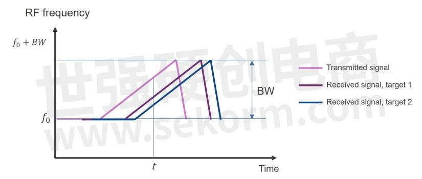
Figure 1 Transmitted and received radar signals (2 targets).
After performing an FFT (Fast Fourier Transformation) two separate baseband frequencies (frequency shift) corresponding to each target are obtained.
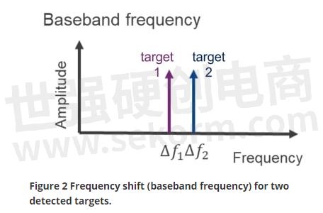
Figure 2 Frequency shift (baseband frequency) for two detected targets.
The closer the two targets, the smaller the difference between the baseband frequencies ∆f1 and ∆f2. At a certain point, the radar system will not be able to separate them anymore. This minimum frequency shift/distance corresponds to one FFT bin. The minimum frequency difference ∆f that can be resolved for an observation time Tc is:

∆f can be improved (i.e. minimized) by increasing the observation time.
The distance between targets ∆R is directly related to ∆f:

With c being the light velocity.
Where S is the slope of the transmitted radar signal (chirp rate in Hz/s). As the bandwidth is the product of the slope of the signal and its duration, the range resolution dres can be written as a function of the signal bandwidth:

The bandwidth of the radar chip will therefore have a direct influence on the achievable range resolution:
Table 1 Range resolution vs. radar signal bandwidth.

A large bandwidth will be needed for applications which require high resolution, for example for imaging radar. Yet, other applications like long-range radar do not need and accuracy in the order of magnitude of centimeters, so a smaller bandwidth would be enough. This is important to consider, as the maximum radar range is inversely proportional to the bandwidth:

For a given sampling rate Fs, increasing the bandwidth will reduce the range of detection.
1.2 Field of view
It is also important to determine the direction of the target (bearing) in an unambiguous way. This is only possible within the field of view (FOV) of the radar, which defines the angular coverage of the radar in azimuth (horizontal plane) and elevation (vertical plane).

Figure 3 Field of view (3D) of a front radar.
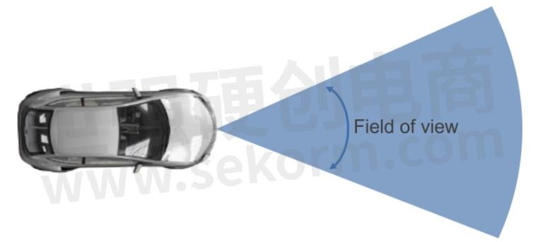
Figure 4 Horizontal (azimuth) field of view of a front radar.
Automotive radars use multiple receiving antennas, to determine the angle of arrival (AoA) of the reflected signal, and thus the angular position of the obstacles. Therefore, the geometry of the antenna array will be a limiting factor of the field of view.
If a single transmitting antenna is considered, the FOV will be determined by the geometry and radiation properties of the receiving antennas. Let us consider the case of two receiving antennas separated by a distance d.
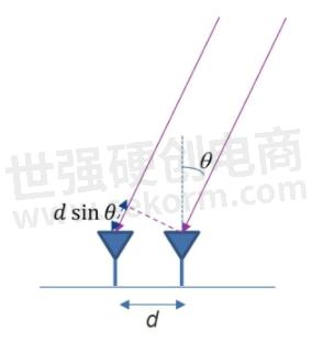
Figure 5 Receive antennas for AoA determination.
The angle of arrival of the signal can be calculated by comparing the phase shift of the signal received by each of the antennas. The phase shift in the received signal depends on the frequency (wavelength) and the distance between the antennas, as shown in Figure 6:

The angular range for unambiguous measurement of the angle of arrival is the range in which the phase difference varies monotonously from -180° to +180°, so the theoretical FOV, from a purely geometric point of view, is given by:

The maximum field of view is achieved when all angles of arrival from -90° to +90° can be detected. This is the case when the distance between the antennas equals half of a wavelength at the frequency of operation, that is:  .
.
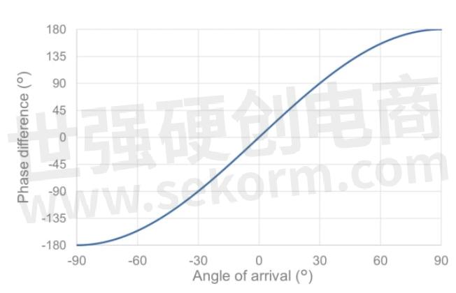
Figure 6 Phase difference for two receive antennas, d = λ/2.
In the case of automotive radar at 77GHz, the theoretical FOV can be maximized using a separation between the antennas of approximately 2mm. This is assuming the antennas used are isotropic radiators. In real life, the field of view will be further limited by the radiation patterns of the antennas.
Let us consider now that the receiving antennas are two uniform linear arrays of patches as shown in Figure 8.
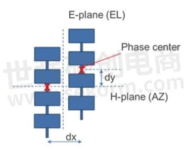
Figure 7 Linear patch arrays as receive antennas for AoA determination in azimuth and elevation.
In this case, the antenna pattern in azimuth is very wide (corresponding to a patch antenna), so that its influence on the FOV is limited. The main limiting effect will be the separation dx between the rows, and the FOV can be calculated using eq. (6).
For the elevation FOV, all the patches in a vertical row are considered as a single antenna. To calculate the theoretical FOV we need to consider the phase center of the row (that is, the imaginary point where the total radiation of the row is originated). The theoretical FOV in elevation will be limited by the vertical separation between the phase centers of each vertical row (dy). If this separation is half a wavelength, we could in principle get the maximum FOV. Yet, in this case the half power beamwidth (HPBW) of the antenna is much smaller (~20-25°), so that the detection would not be possible be outside the antenna beam. In this case, the radiation pattern will be the limiting factor of the FOV.
1.3 Angular resolution
As in the case of the range resolution, it is also important to be able to distinguish between two separate targets placed at different angles (bearings), but at the same range. Here, the frequency shift due to the signal delay cannot be used to identify the signals from each of the targets. Again, special diversity is needed, with multiple antennas at different locations.
The angular resolution θres indicates then the minimum angular separation that can be resolved by the radar. For a single transmit antenna it can be calculated as:

N being the number of receive antennas and θ the angle of arrival. The angular resolution is at is maximum for bearings close to the boresight direction (θ = 0°):

If we consider that the antennas are separated  , to maximize the FOV, the angular resolution will be independent of the frequency, and be only determined by the number of receive antennas.

The resolution can therefore be increased by increasing the number of antennas. This is only possible by adding more channels to the radar MMIC transceiver. The resolution can be further improved by using multiple transmit antennas for MIMO (Multiple Input, Multiple Output) and super-resolution post processing.
1.4 Conclusion
In this entry, the parameters that determine the accuracy of a radar system have been presented. The range resolution is directly linked to the performance of the radar transceiver, while the angular resolution and field of view will also depend on the geometry of the antennas used in the radar system.
- |
- +1 赞 0
- 收藏
- 评论 0
本文由翊翊所思转载自Renesas,原文标题为:Radar transceivers: key components for ADAS & Autonomous Driving 4.- Radar resolution: How accurate can a radar be?,本站所有转载文章系出于传递更多信息之目的,且明确注明来源,不希望被转载的媒体或个人可与我们联系,我们将立即进行删除处理。
相关推荐
Radar transceivers: a key component for ADAS & Autonomous Driving-Basics of FMCW radar
This entry has provided an overview of the operating principle of the FMCW radar, used in automotive applications, and its implementation using MMICs and MCU/SoC.
How to Connect the Antennas
We will focus on how to connect a monolithic microwave integrated circuit (MMIC) radar transceiver to the antennas in a way that guarantees an efficient transfer of the signals.
【经验】如何优化AD/ADAS的SoC AI性能?
在开发面向车载AI设备的SoC时,确认搭载的加速器能否在实际顾客产品中所需的DNN中提供足够的性能,并且功耗是否在可接受范围内,已成为迫切的问题。瑞萨(RENESAS)将利用PPA Estimator的高度精确性能寻找最佳配置以开发高性能、低功耗的车载AI加速器。
用于汽车雷达传感器的STRADA431 24 GHz收发器微波单片集成电路
描述- STRADA431是一款专为汽车雷达传感器设计的24 GHz收发器MMIC,具有AEC-Q100认证。该产品具备单通道发射器、低相位噪声VCO、三个单端接收通道和低噪声系数。适用于24至24.25 GHz的汽车雷达应用。
型号- STRADA431-TR,STRADA431
Renesas Unveils RAA270205, the First 4x4-channel 76-81GHz Automotive Radar Transceiver with High Accuracy and Low Power Consumption
Renesas is entering the automotive radar market with the introduction of a 4x4-channel, 76-81GHz transceiver designed to meet the demanding requirements of ADAS and Level 3 and higher autonomous driving applications. It will be available in 1Q/2023 in sample quantities, with commercial production planned for 2024.
Antennas for Automotive Radar
In previous issues of the radar blog, we have reviewed the main characteristics of MMIC transceivers for automotive radar. Yet, an aspect still needs to be covered: how to integrate the MMIC on the radar module’s PCB, and what should we consider to optimize the interface between the chip and the antennas.
STRADA770 76-81GHz汽车雷达用微波单片集成电路收发器(4RX/3TX)
描述- STRADA770是一款针对汽车雷达应用的76-81GHz毫米波收发器,具有可扩展架构、BIST结构和Bicmos9MW/SiGe:C工艺。该产品支持AEC-Q100认证,具备三通道发射器、四通道接收器、数字控制输出功率、可配置FMCW调制器等特性,适用于多种汽车雷达应用。
型号- STRADA770
24GHz雷达传感器-系列扩展,带双发射器和四接收器,用于汽车应用
描述- BGT24Axx系列是市场上最高集成度和最广泛的24GHz雷达收发器产品组合,相比离散组件,可节省约30%的板空间。该系列包括两个新的MMIC,BGT24AT2(双发射通道)和BGT24AR4(四接收通道),可提高雷达功能的通道数量。该雷达传感器广泛应用于工厂、仓库、私人住宅的安全和防盗系统,以及ADAS(高级驾驶辅助系统)的汽车雷达解决方案,确保驾驶安全。
型号- BGT24AT2,BGT24AXX,BGT24AR4
IAM-20685用于ADAS和自动驾驶应用的汽车6轴MotionTracking®MEMS器件
描述- IAM-20685是一款集成了3轴陀螺仪和3轴加速度计的6轴运动跟踪MEMS器件,适用于ADAS(高级驾驶辅助系统)和自动驾驶应用。该器件具有小型化设计,尺寸为4.5x4.5x1.1mm³,支持可编程的全量程范围,并具备高可靠性和安全性。
型号- IAM-20685
LX Semicon电机驱动器&MCU选型表
LX Semicon电机驱动器&MCU选型表包含32位通用MCU、2ch H-桥电机驱动器、三相电机驱动器三个品类,主要包含以下参数,Operating Temperature(℃):-40℃ ~ 85℃;Power (V):3.9 to 5.5V、2.7 to 5.5V、Max.20V、Max.28V;competitor:Toshiba、Renesas、TI。
|
产品型号
|
品类
|
封装/外壳/尺寸
|
Power (V)
|
Grade certification standard
|
competitor
|
External High Speed OSC(MHz)
|
External Low Speed OSC(KHz)
|
Operating Temperature(℃)
|
Maximum Frequency(MHz)
|
SRAM(Kbyte)
|
|
SW31100
|
32位通用MCU
|
LQFP 64
(10*10, 0.5pitch)
|
3.9 to 5.5V
|
IEC 60730 supported
|
Toshiba
|
10MHz
|
32.768kHz
|
-40℃ ~ 85℃
|
35MHZ
|
12 Kbyte
|
选型表 - LX Semicon 立即选型
REF66012 – 参考设计 ADAS SoC用 PMIC解决方案
描述- 本资料介绍了ROHM公司为ADAS SoC设计的PMIC(电源管理集成电路)解决方案。方案包括BD96801Q09-CE2四通道DC-DC转换器和BD9S303MUF-CE23A同步降压转换器,旨在提供高效率和高可靠性。该方案适用于智能前视摄像头(IFC),集成200万像素摄像头和多毫米波雷达,支持L2级前向ADAS功能。它采用Horizon Journey2芯片和Infineon TRAVEO II系列CYT4BF微控制器,实现AEB、ACC等功能。此外,还提供了详细的规格和应用说明。
型号- BD96801Q09-CE2,BD9S303,BD9S303MUF-CE2,BD96801Q09,BD96801,BD9S303MUF
Rohm Automotive Lighting Solutions Will Focus on the ADAS Space and Autonomous Driving Systems
LED technology has brought with it several breakthroughs that address design limitations of the lamp unit to achieve a variety of form factors, from thin, compact types to unique packages specific to individual car manufacturers. These specially designed lamp modules utilizing multiple LEDs add new features and functions not available with conventional lighting systems.
【产品】低功耗全高清ADAS专用低功耗SoC芯片SGKS6802
森国科SGKS6802是一款针对高级辅助驾驶(ADAS)、流媒体后视镜、夜视系统、透雾透霾及图形图像识别与处理等产品开发的ADAS专用低功耗SoC芯片,1080P@30fps+720P@30fps双路码流H.264编码及高质量的ISP处理。
电子商城
现货市场




登录 | 立即注册
提交评论