Data Center Ethernet on the Move to 224Gbps

Large-scale internet data centers are the fastest growing market for optical interconnection technology and innovation, with 70% of all internet traffic occurring inside the data center, driven by increasing machine-to-machine communication. In this paper,KEYSIGHT will talk about Data Center Ethernet on the Move to 224Gbps.
A typical data center network structure based on CLOS architecture (aka leaf-Spine) is shown in Figure 1.

Figure 1. Network architecture of a typical hyperscale data center
A data center internal network usually has 3 to 4 levels from bottom to top.
Moving through the levels from the Server to the Core, the reach of each interconnection increases from a few meters to several kilometers, necessitating changes of technology and interface standards.
Server Cabinets / Top of Rack Switch (TOR): At the lowest level, individual server racks are connected to TOR switches at the top of the cabinet. Current data centers generally deploy 25G networks, with some artificial intelligence (AI) applications utilizing 50G speeds. Over the next few years 100G, 200G and 400G speed interconnection technology will be employed. Connection distances are short, being either within the cabinet or to adjacent cabinets and generally less than 5 meters. A typical interface technology used today is direct attach copper cable (DAC) or active optical cable (AOC). As speeds evolve to 400G and 800G the reach of DACs will be too short and active electrical cable (AEC) will be used instead.
TOR to Leaf Switch: The second level is the connection from TOR switches to Leaf switches. This distance ranges up to about 50 meters, using 100G interconnection technology now and moving to 200G and 400G speeds and in a few years to 800G. Typically optical modules such as 100GBASE-SR4 or 200GBASE-SR4 combined with multi-mode optical fiber are used today along with NRZ (Non-Return to Zero) signaling. For this level and the higher-level interconnections, the move to 200G and 400G also changes the signaling to PAM4 (Pulse Amplitude Modulation 4 level).
Leaf to Spine: The leaf to spine connection may be within campus, or adjacent campus, with connection distance up to 500 meters. Using similar interface rates as TOR to Leaf, 100G moving to 200/400G now and 800G around 2023. With the longer reach, the technology moves to single mode fiber and often several parallel fibers utilizing modules such as 100G-PSM4, 100G-CDWM4 and moving to 200GBASE-DR4 and 400GBASE-DR4.
Spine to Core: As the reach increases further up to 2 kilometers, the cost of fiber starts to be a consideration, and so wavelength division multiplexing technology is often used to send data via several different optical wavelengths on one fiber, today using modules such as 100GBASE-LR4, 100G-CWDM4, 400GBASE-ER4/-LR4/-FR4 etc.
Data Center Interconnect (DCI): This is generally a connection between several adjacent data centers for load balancing or disaster recovery backup. The distance may range from tens of kilometers to around a hundred kilometers. Over this longer distance dense wavelength division multiplexing is employed and, more recently, coherent communication is being used in preference to direct detect technologies. Telecom operators have deployed 100G coherent technology for many years in long-distance (hundreds of kilometers) applications. Speed increases into 200, 400, 800G technology is also ongoing. For DCIs, since the transmission distance is not as far as the telecom applications and is mainly point-to-point, coherent transmission is feasible using pluggable module technology with smaller size and power consumption, such as 400G-ZR.
THE DEVELOPMENT OF DATA CENTER INTERCONNECTION TECHNOLOGY
As shown in Figure 1 there are several different electrical and optical interconnection technologies in use in the data center, and they are continuously evolving.

Figure 2. Technology for improving the speed of Ethernet interconnections in the data center
The speed of each interface can be achieved by more than one method or interface standard, each having different trade-offs between performance, reach, power consumption and cost.
There are three technical directions to increase the speed of the interconnection interface (Figure 2):
The first method is to directly increase the data or baud rate of the channel, e.g. the development from 155 Mb/s to 622 Mb/s in the SDH/SONET era, or 100 Mb/s Ethernet ports all the way to 10 Gb/s Gigabit Ethernet ports. Often the baud rate improvement required can be ahead of the available technology at the time so other methods have been used.
The second method is to increase the number of channels. This has the advantage of keeping the baud rate constant but does bring additional cost and complexity to the interface design. For example, the Ethernet interface transition from 10 Gb/s to 40 Gb/s employed a 4 x 10 Gb/s channel approach in preference to a single-channel 40 Gb/s link and its high cost of implementation. The same approach was used to move to 100G Ethernet, using initially 10 x 10 Gb/s channels, and later 4 x 25 Gb/s channels, which has become the mainstream 100G Ethernet interface implementation. For the electrical interfaces this approach always means more channels for the devices and circuit boards, introducing crosstalk as a new design consideration. For the optical interface, multiple channels can be implemented as parallel multi-mode or single-mode fibers for short-distance transmission and by using wavelength division multiplexing (WDM) on a single fiber for longer-distance transmission. The type and number of available fibers per port is usually set by the existing fiber infrastructure, governing the deployment of higher speed optical interfaces in an existing datacenter. Generally, 4 or 8 wavelengths are used in WDM (5 nm spacing) or CWDM (20 nm spacing). Some leading-edge research is studying few-mode multi-core fibers where multiple cores are made from a single fiber to realize spatial multiplexing transmission.
The third method is to use a more complex modulation method. Data rates up to 25 Gb/s have used NRZ signaling. When the industry put forward the technical requirements for 400G Ethernet, it was challenging to increase the data rate to 53 Gb/s at that time, especially in the electrical domain, pushing the limits of device bandwidth, packaging, and PCB design. Increasing the number of channels increases the space requirements and power consumption of solutions and does not help in the overall cost/bit reduction target for data centers. As a result, PAM4 complex modulation was proposed over NRZ. PAM4 4 level modulation enables each data symbol to carry 2 bits / symbol, doubling the interface data rate for the same number of channels and baud rate.
Complex modulation techniques are commonly used in the field of long-distance coherent optical communication. For example, 100G coherent communication generally uses QPSK modulation, where one symbol can carry two bits; while 400G coherent communication uses 16-QAM modulation, with 4 bits per symbol. In wireless communications and new coherent implementations 256-QAM is used with 8 bits / symbol throughput.
All of the methods above have been used at different times to increase data throughput in the data center. Figure 3 summarizes the development of electrical and optical port data rates for both the 100G and 400G Ethernet standards. In addition to the data rate increase, the transceiver form factor and internal architecture has also evolved to reduce size and power consumption.
MOVING TO 800G ETHERNET
Development has commenced for next Ethernet speed class - 800G. The first generation of 800G will employ 112 Gbps per lane, enabling 200/400/800G links, and the second generation will introduce 224 Gbps per lane for up to 1.6T links. Standards organizations have all commenced projects or working groups for 800G e.g.
• OIF Common Electrical I/O (CEI)-112G and Common Electrical I/O (CEI)-224G
• IEEE 802.3 Beyond 400 Gb/s Ethernet Study Group
• 800G Pluggable MSA (Multi-Source Agreement)
• OSFP MSA 200G/lane Electrical Signaling Group
Figure 4 shows the technical roadmap of 800G optical interconnection as described in a white paper issued by the 800G-MSA standard organization. The 800G Ethernet optical ports will mainly have two implementation methods. One will use 8 parallel single-mode fibers (e.g. 800G-PSM8) for short-distance connections up to about 100 meters at 100G per fiber. The other will use either 4 parallel single-mode fibers (e.g. 800G-PSM4 or 800G-DR4) or 1 single-mode fiber with WDM (e.g. 800G-FR4) for medium-distance connections up to about 2 km at 200G per fiber or per wavelength. The IEEE802.3db working group is also discussing the feasibility of using 8 channel multimode fiber to achieve short distance (tens of meters) 800G transmission, but currently it is limited by the bandwidth of commercially available VCSEL lasers. The feasibility of its industry acceptance remains to be seen.

Figure 4. The technical roadmap of optical interconnection organized by the 800G Pluggable MSA 2
The implementation of a typical 800G optical interconnection is shown in Figure 5, as either an 8 channel optical port solution or a 4 channel optical port solution. The yellow blocks in the figure indicate the addition of 800G Ethernet to the currently available 400G Ethernet technology.
The 800G-PSM8 or -DR8 implementation is not very different from 400G-DR4, except that the number of optical channels has doubled. There is already mature chip and industry supply-chain support. At the electrical interface, the previous 400G Ethernet used 8 channel 50 Gbps connections. For 800G, the rate of the electrical interface between the 800G Ethernet switch chip and the optical module must be increased to 100 Gbps per channel so that 8 channels can provide 800 Gbps overall. 800G Ethernet optical modules can also use QSFP-DD or OSFP packages commonly used for 400G optical modules, but the performance needs to be improved to support higher electrical interface rates. Since the end of 2020, chip manufacturers have released CDR/DSP chips supporting single-channel 100 Gbps and higher-performance QSFP-DD and OSFP packages. Therefore, the technology is available to implement 8 x 100 Gbps electrical and optical ports to achieve 800G connections. If power consumption and cost can be controlled, this solution could be commercialized relatively quickly.
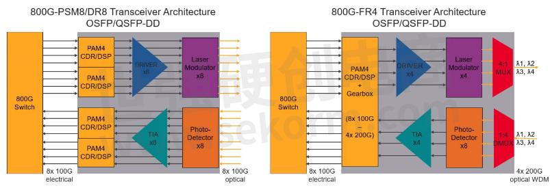
Figure 5. Typical implementations of 800G optical interconnection
The 800G-FR4 4 channel solution brings a new challenge, because the optical module also needs a gearbox to convert 8 channels of 100 Gbps electrical signals into 4 channels of 200 Gbps electrical signals. This then drives 4 optical modulators that can support the corresponding 200 Gbps rate. It is necessary to define a new optical port standard and devices that can handle the higher bandwidth such as DSP, driver, modulator, TIA, etc. At present, this technology is still in the pre-research stage, with modulation mode, baud rate, system bandwidth, link budget, bit error rate, FEC mode, etc. all being explored and discussed.
TECHNICAL CHALLENGES OF 800G ETHERNET
The speed of the previous 400G electrical lanes is doubled to 112 Gbps for the first generation of 800G Ethernet and goes to 4 times (224 Gbps) in the second generation. Interface chips, DSP chips, packaging, connectors etc. all will need performance improvements or new designs to work at the higher speeds. There are already some corresponding standards in the industry that define 112 Gbps electrical ports, such as the OIF CEI-112G family of implementation agreements and the IEEE 802.3ck standard. Both standards bodies define electrical link requirements for various distances or reaches.
- |
- +1 赞 0
- 收藏
- 评论 0
本文由董慧转载自Keysight,原文标题为:Data Center Ethernet on the Move to 224 Gbps,本站所有转载文章系出于传递更多信息之目的,且明确注明来源,不希望被转载的媒体或个人可与我们联系,我们将立即进行删除处理。
相关推荐

Keysight‘s Open RAN Studio Selected by Kyocera To be Used for Radio Units Validation To be Used for Radio Units Validation in Compliance to O-RAN Specifications
Keysight‘s Open RAN Studio software combines visibility, validation and performance test capabilities across RF and protocol measurement domains. It is part of the company‘s integrated solution portfolio of solutions that address test requirements from the edge of the RAN to the 5G core (5GC). End-to-end system testing helps to simplify complex multi-vendor network environments designed to deliver a wide range of connectivity service offerings.

Keysight eye contour软件眼睛轮廓功能,仅需设定一定误码率BER即可快速生成眼图
眼图是查看抖动的最常用方式之一。在更新到最新的Infiniium 11.40 Core Software后,您将可以通过在任何NRZ信号上使用Keysight eye contour软件来减少你的测量时间,在眼图上生成出不同误码率下的误码率预测等高线。

Keysight O-RAN Solutions Added to CableLabs‘ 5G Lab for Support of 2023 5G Challenge
Keysight is delighted to support CableLabs‘ 5G Lab with expanded testing capabilities with complete interoperability and conformance solutions portfolio. Keysight equipment allows 5G Challenge contestants to confirm that their subcomponents are interoperable with the subcomponents of other vendors.

BV0014B BenchVue LCR仪表控制和自动化应用程序发行说明
BenchVue LCR测量仪控制与自动化应用程序2023.1版本发布,主要更新包括稳定性、可用性和性能的增强。该版本针对Windows 10(64位,版本1809或更高)操作系统,要求Intel Core i5(或同等性能)处理器、8GB RAM和900MB可用存储空间。新版本修复了缺陷,提高了稳定性、可用性和性能。支持多种Keysight BenchVue仪器。
KEYSIGHT - BENCHVUE LCR测量仪,BENCHVUE LCR METER,BV0014B

是德科技 N1090A、N1092A/B/C/D/E 和 N1094A/B DCA-M 光电信号采样示波器
KEYSIGHT - DCA-M光电信号采样示波器,100GBASE-SR4,1090A-EEC,N1092-206,N1090A-1CN,N1090A-1CM,N109X,N1090AU-200,N1092-168,N1010A,N1090AU-140,N1092A,N1090AU-160,N1094B,N1094A,N1090A-140,N1090AU-180,N1092E,N1090A-160,N1092D,86100,861XX,N1092C,N1090A,N1090A-180,N1092B,N1090A-204,N1092,N1090A-200,N1094,N1090AU-204

Keysight i7090 with PathWave Test Executive for Manufacturing
Keysigt’s FlexiCore Parallel ICT system and i7090 Massively Parallel ICT system are automated inline handler systems designed specifically for high throughput automated inline test applications.

M9536A AXIE嵌入式PC控制器
Keysight Technologies推出的M9536A AXIe嵌入式PC控制器是一款高性能的AXIe兼容控制器,具备Gen 2 PCIe链路至AXIe背板,支持快速数据传输。该控制器采用Intel Xeon EP Quad Core L5518处理器,提供16 GB RAM选项,并预装Keysight I/O库和操作系统,旨在缩短测试系统开发时间。它适用于航空航天、通信、计算、电子测试和半导体测试等领域,具有一个插槽的紧凑设计,并支持与LXI仪器的集成。
KEYSIGHT - AXIE EMBEDDED PC CONTROLLER,AXIE嵌入式PC控制器,M9505A,M9536A-WE3,M9536A,M9536A-M16,M9502A,M9536A-WE6,高能物理学,ELECTRONIC TEST,计算,COMMUNICATIONS,航空航天,电子测试,半导体测试,AEROSPACE,DEFENSE,COMPUTATION,通信,SEMICONDUCTOR TESTING,HIGH-ENERGY PHYSICS,国防
Ixia Novus SFP28/QSFP28高密度100/25/10GE负载模块
KEYSIGHT - 负载模块,LOAD MODULE,905-1004,905-1005,905-1007,944-1164,100GBASE-SR4,905-1008,905-1009,SFP28-SR-XCVR,942-0068,940-0010,940-0011,25GBASE-SR,940-0013,940-0014,940-0015,940-0016,942-0067,944-1232,944-1156,944-1231,QSFP28-PSM4-XCVR,944-1117,SFP28-LR-XCVR,948-0037,QSFP28-SR4-XCVR,100GBASE-CR4,905-1011,905-1012,100GBASE-LR4,905-1025,905-1026,944-1147,944-1140,QSFP28-LR4-XCVR,991-2032,991-2033,SFP28-2M-CBL,942-0128,905-1063,905-1064,942-0088,905-1065,905-1066,942-0092,25GBASE-CR,25GBASE-LR,QSFP28-DR1-XCVR,948-0059,948-0058,948-0055,992-0072

是德科技连续两年荣膺AspenCore 2023中国IC设计成就奖之“年度杰出测试测量供应商”
凭借在芯片测试领域卓越的产品创新能力,以及全方位的客户服务等方面的突出影响,是德科技荣获ASPENCORE评选的2023中国IC设计成就奖之“年度杰出测试测量供应商”。是德科技已经连续第二年凭借实力荣膺该奖项。
M9037A PXIe嵌入式控制器2.4 GHz四核数据表
KEYSIGHT - PXIE EMBEDDED CONTROLLER,PXIE嵌入式控制器,Y1264A,Y1265B,M9010A,Y1265A,Y1262A,Y1260A,Y1261A,M9037A-W16,M9037A,Y1206A,M9018B,M9019A,M9037A-M08,M9037A-M16,M9037A-WE6,M9037A-WE3

Keysight Enables AI-LINK to Accelerate 5G Private Network Deployments in Smart Warehouses
Keysight Technologies announced that AI-LINK has selected Keysight‘s 5G test tools for end-to-end performance validation of cloud-native 5G RAN equipment in a digital twin laboratory environment, which accelerates 5G private network deployments for large-scale smart warehouse applications.

是德科技助力爱瑞无线获得O-RAN首枚O-DU前传一致性证书,提振运营商对Open RAN架构的信心
2023年3月29日,Keysight日前宣布,该公司的KORA解决方案助力爱瑞无线获得O-RAN 联盟颁发的首枚O-DU前传一致性证书。该证书由中关村泛联院OTIC认证中心颁发。是德科技提供先进的设计和验证解决方案,旨在加速创新,创造一个安全互联的世界。

【产品】基础型直流电源E36100B,提供高达5A的电流或100V的电压
Keysight E36100B 系列基础型直流电源拥有紧凑的结构、可视角度很宽的高对比度 OLED 显示屏、现代 USB 和 LAN(LXI Core)连通性。高精度小电流测量功能可以满足苛刻的测量要求。内置过压和过流保护功能可以为被测器件提供良好的保护,同时内置的过温保护功能还确保了电源自身的安全。

Keysight Enables First O-RAN Open Distributed Unit Fronthaul Certificate for ArrayComm through APOP
Keysight Technologies has enabled ArrayComm to obtain the first O-RAN ALLIANCE Fronthaul Certificate of Conformance for its open distributed unit (O-DU) with the Keysight Open RAN Architect (KORA) solutions. The certification was issued by the Asia & Pacific OTIC in PRC (APOP).

是德科技O-RAN解决方案被CableLabs 5G实验室选中,用于支持2023年度5G行业挑战赛
是德科技日前宣布,KORA解决方案已被 CableLabs 5G 实验室选中,用于在 2023 年度 5G 行业挑战赛期间验证O-RAN组件的互操作性。该挑战赛由美国国家远程通信和信息管理局(NTIA)和美国国防部联合主办。

电子商城


现货市场


授权代理品牌:集成电路


授权代理品牌:分立元件


授权代理品牌:接插件及结构件


授权代理品牌:部件、组件及配件


授权代理品牌:电源及模块


授权代理品牌:电子材料


授权代理品牌:仪器仪表及测试配组件


授权代理品牌:电工工具及材料


授权代理品牌:机械电子元件


授权代理品牌:加工与定制


登录 | 立即注册
提交评论