CRU software instruction


1 CRU Introduction
Compass Receiver Utility (CRU) is professional Windows-based configuration software developed by ComNav Technology. Using the CRU software, you can convert the original observation data (cnb) into Rinex format; configure the parameters of the static collection of the receiver (only the receiver of the K7 platform is supported, the receiver of the K8 platform needs to use webUI configuration); and you can view the satellites tracked by the receiver Status; download static data (only supported by some old models of T300 receivers).
1.1 CRU installation
Download and install CRU software from the link below (ensure the driver is properly installed in your PC):
https://www.comnavtech.com/companyfile/4/
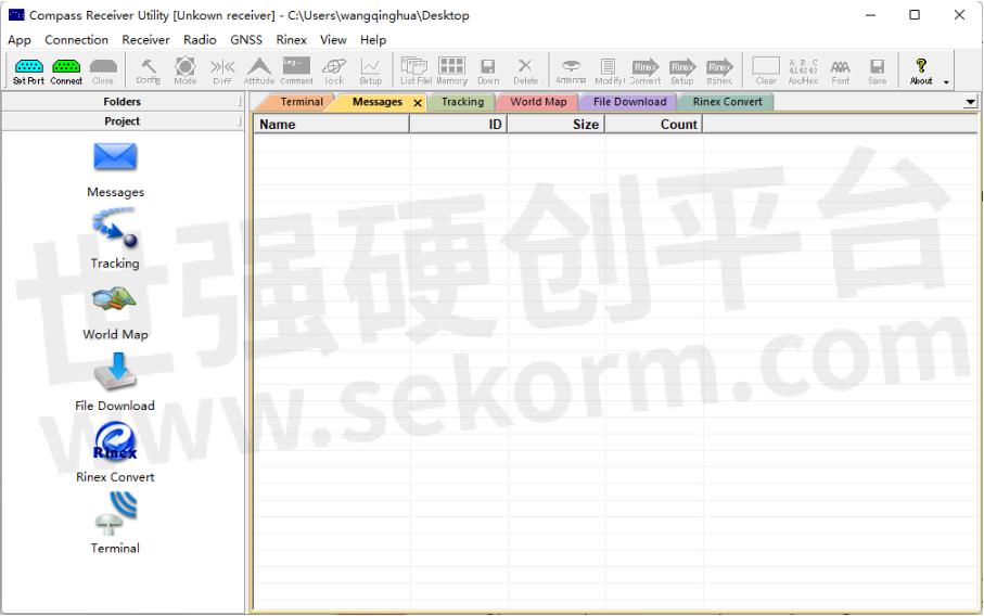
1.1 User Interface
This section describes the user interface and main menus of Compass Receiver software.
• Menu Bar: contains all functional menus.
• Standard Toolbar: quick access to the frequently used functions, including device connection, configuration, static data download, rinex convert, and data log.
• View Area: the main display window.
• Navigation Pane: you can browse the folders of your computer and check some main functions of CRU software.
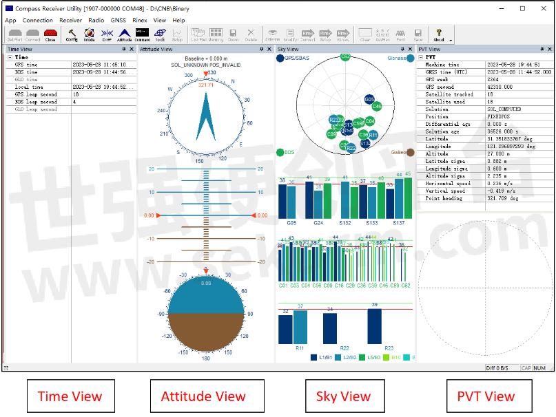
• Float window: shows the information of sky View, PVT View, and Time View, go to menu Bar -> View to active float window.
• Status box: contains the display current cursor indication, differential data flow, etc.
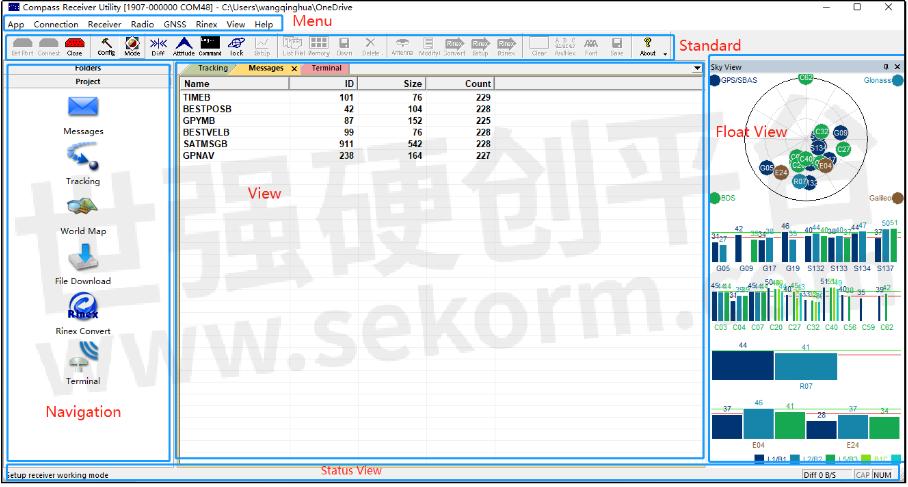
1.2.1 Menu Bar & Standard Bar
The menu bar includes App, Connection, Receiver, Radio, GNSS, Rinex, View, and Help. The main functions of each menu are described below:
![]()
• App: Click to exit the CRU software.
• Connection: Support three connection methods: Serial port, TCP Client, Data file, connect and disconnect the OEM board, and setup differential corrections.
• Receiver: Include some receiver settings, like Attitude settings, Work mode, and Lock/Unlock.
• Radio: Including CDL3/CDL5 configuration settings and T300 radio work mode settings.
• GNSS: Display or disable the GPS/BDS/GLONASS/GALILEO constellations in the Sky View.
• Rinex: Rinex converts settings.
• View: Display or disable the floating views.
• Help: Help and about compass solution.
The Standard Bar includes Connection Settings, Receiver Settings, Static data download, Rinex convert, Datalog, and About.
The main functions of each Standard bar are described below:
![]()
• Connection Settings: Setport, connect and disconnect.
• Receiver settings: Static configuration, work mode, differential corrections setting, Attitude setting, Command, Satellite lock/unlock, and Setup.
• Receiver: Include some receiver settings, like Attitude settings, Work mode, and Lock/Unlock.
• Static data download: View static file list, read receiver memory, download static file, delete static file.
• Rinex settings: Antenna setup, antenna modify, rinex setup, rinex convert, binex convert.
Data log: Clear current message output in the view page, ASCII/HEX display switch, display font setting, and save the data log.
About: about compass solution.
1.3 Main function introduction
The following will mainly explain some common functions for OEM boards.
1.3.1 Connection setup
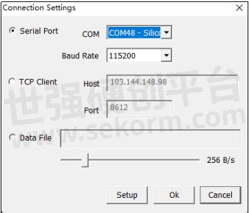
Connection setup supports three methods: Serial Port, TCP Client, and Data file reading, for the OEM board, select the Serial Port method.
Click Set port in the Standard bar or click Connection->Settings in the Menu bar, and you will go to Connection setup.
►Serial port: This is used to connect the com port of the receiver, you need to choose the proper baud rate (CRU supports 2400, 4800, 9600, 19200, 38400, 57600, 115200, 230400, 460800, 921600), click Setup->Connect or click OK directly to connect the OEM board, click Cancel to cancel Connection setup.
1.3.2 Differential source setup
RTK, send the carrier phase collected by the base station to the user receiver and calculate the coordinates by calculating the difference. RTK (Real-time differential positioning) is a measurement method that can obtain centimeter-level positioning accuracy in real-time in the field, and its appearance has greatly improved the efficiency of field operations.
Generally, the OEM board is the single status when it doesn’t receive differential corrections, if you want to set the OEM board as a rover and get differential corrections, you can click the Diff on the Standard Bar to set the Diff source.
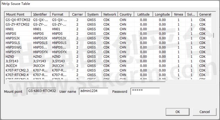
►Diff: This is used to receive the differential corrections to do RTK, enter the Host IP and port, check on the Ntrip option, then click Connect to select one mount point.
Save RTCM: You can save RTCM data from the differential screams while doing RTK.

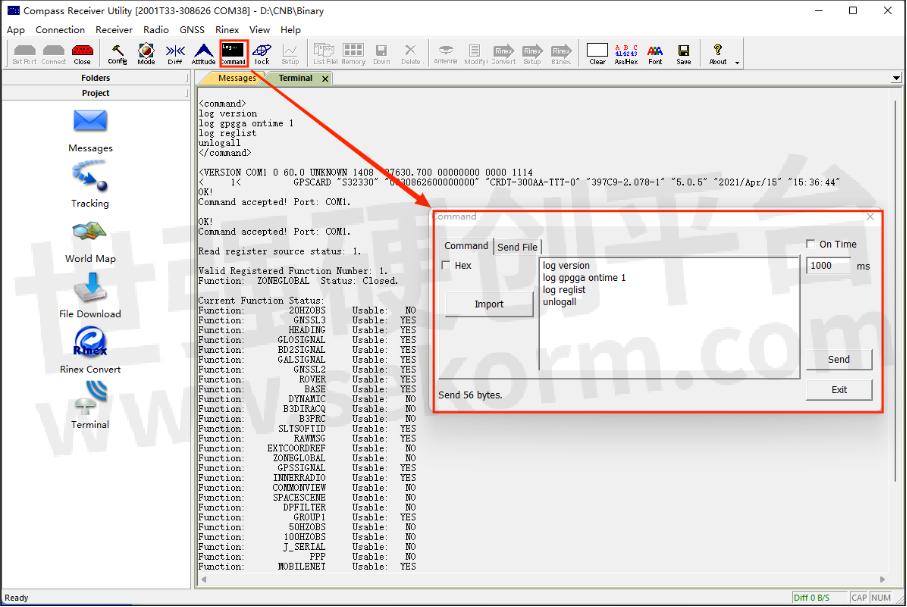
►Command: CRU software supports entering commands manually, you can create a command file (*.txt, or *.bin format), and click Import to import the command file, the commands will be listed in the Command view.
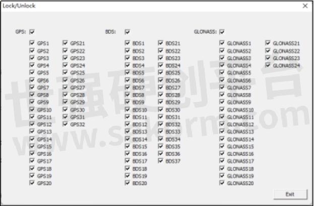
►Lock: When you open Sky View in the floating view, you will see all satellite constellations, you can disable or enable the whole satellite system or a specific satellite in Lock, and the corresponding satellites will show in Sky View.
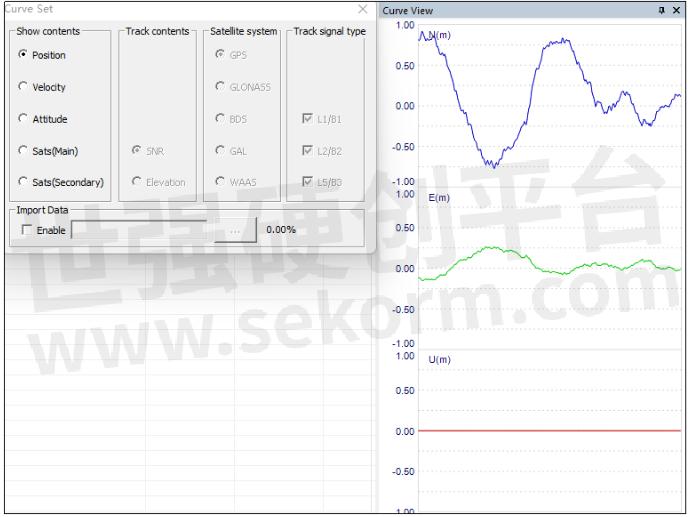
►Setup: Only Curve View is enabled, this setup will be highlighted and able to be configured, you can check the Position, Velocity, Altitude, satellite SNR and elevation.
1.3.3 Radio Settings
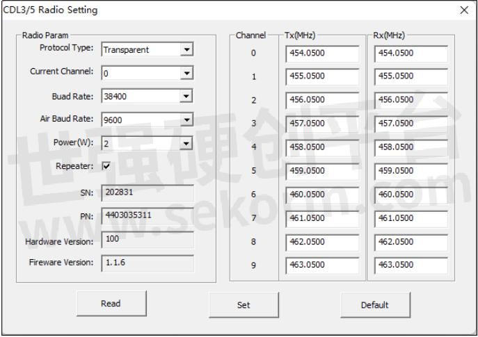
►CDL3/CLD5 settings: When CDL3/CDL5 is connected in CRU software, you can use the Radio setting to configure the parameters, click Read to get the current parameters, Click Default to restore to the default parameters, after changing the parameters, click Set to save the settings, the default setting is as below:
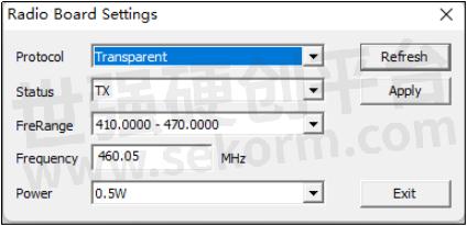
►T300: When the receiver (K7 platform) is connected, you can use this option to set up radio work mode.
Protocol: Supports Transparent, TT450S(Trimble), MAC (Medium Access Control), South Survey;
Status: TX/RX, TX means to transmit the correction, RX means to receive the corrections;
Frequency range: 410-470MHz, 865-867 MHz;
Power: 0.5w, 1.0w, 2.0w;
Refresh: Click Refresh to get the current radio work mode status;
Apply: After setup radio work mode, click Apply to save the settings.
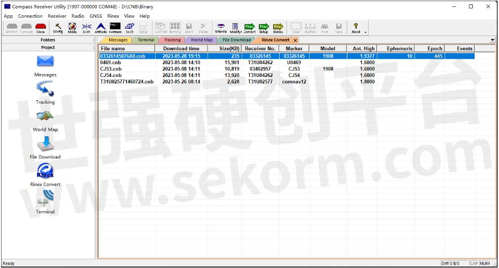
1.3.4 Rinex Convert
CRU software supports converting CNB file to Rinex format, click Rinex Convert in the Navigation bar or in the Menu bar, and the Rinex part will be highlighted and able to set up.
![]()
1.3.4 Rinex Convert
CRU software supports converting CNB files to rinex format, click Rinex Convert in the Navigation bar or in the Menu bar, and the Rinex part will be highlighted and able to set up.
![]()
The Rinex convert steps are as below:
1. Click Folders to browse the static path;
2. Click Rinex Convert in the Project bar; select the cab file which needs to convert;
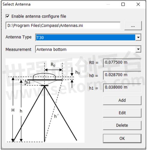
3. Click Antenna in the Standard bar, and set antenna type and measurement method; You can add antenna parameters if you don’t find the antenna you want.
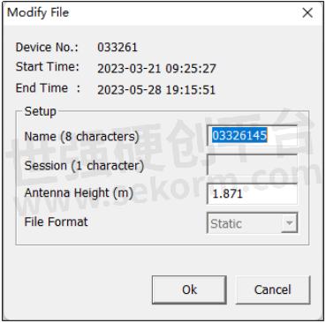
4. Click Modify in the Standard bar to set station name and antenna height;
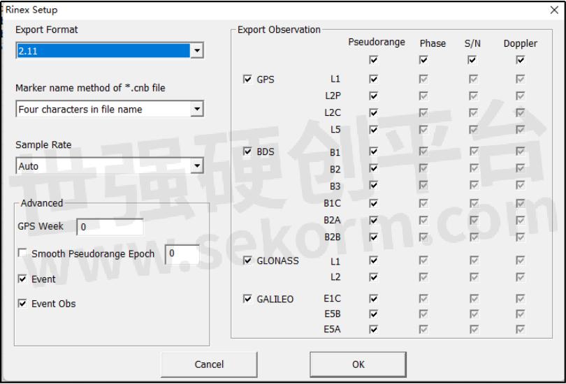
5. Click Rinex Setup in the Standard bar to choose Rinex parameters:
Rinex type: supports Rinex 2.01, 2.11, 3.01, 3.02, 3.03, 3.04.
Marker name method: Supports four characters in the file name, full file name, NMEA + Day (3 character) + Session (1 character)
Sample rate: Auto (default), 1 second, 5 seconds, 10 seconds, 15 seconds, 30 seconds, 60 seconds.
Event/Event Obs: If you convert PPK (dynamic files), you need to check on these two options.
6. Click Rinex Convert in the Standard bar to convert cnb file to a rinex file, the rinex files will be stored in the same path as the cnb file.
1.3.5 Project Bar
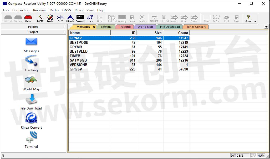
1.Messages
Click Messages to check current output messages of the receiver in the View area, if you send commands in Command, the corresponding messages will show in View area.
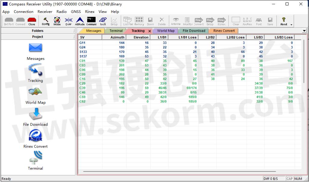
2. Tracking
Click Tracking to check current tracked satellite information, if you check Tracking view, when you go to the Terminal page, there will be some messages output in the View area, it is ephemeris in binary.
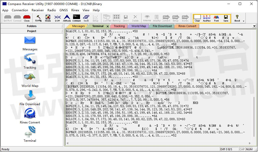
3. Terminal
Click Terminal to check current output message details, and the data log will be highlighted and able to be set up in the Standard bar.
• Clear: Clear all current output messages in the View bar;
• ASCII/HEX: Click to switch output messages between ASCII and HEX;
• Font: Change the display font of the output message;
• Save: Save a file about current output messages, when creating a file, the Save button will be highlighted, which means the file is saving, click the Save button again to stop the file saving.
1.3.6 View
Click View in the Standard Bar to set up the float view, which includes Sky View, Attitude View, PVT View, Time View, Curve View, Sky View Secondary.
- |
- +1 赞 0
- 收藏
- 评论 0
本文由翊翊所思转载自ComNav Technology News,原文标题为:CRU software instruction,本站所有转载文章系出于传递更多信息之目的,且明确注明来源,不希望被转载的媒体或个人可与我们联系,我们将立即进行删除处理。
相关推荐
【经验】北斗三号精密单点定位(PPP-B2b)技术及应用——以司南导航EVK-K8评估套件为例
PPP-B2b是北斗系统首次对外发布的高精度信号,由北斗三颗地球同步轨道(GEO)卫星播发,为用户提供公开、免费的高精度服务。本文将介绍北斗三号精密单点定位(PPP-B2b)技术及应用——以司南导航EVK-K8评估套件为例。
【经验】使用手机控制司南导航K823 GNSS定位模块进行RTK差分定位实验流程
本文是一篇帮助用户使用司南导航K823模块进行RTK 定位实验的快捷操作指南,实验中使用手机app作为上位机软件发送指令控制模块,将司南导航定位模块设置为移动站,运营商基站作为基准站进行的RTK差分定位实验。
司南导航(Comnav Technology)K8系列北斗/GNSS高精度定位模块选型指南
公司介绍 核心技术 K系列模块对比表 高精度模块 数传模块 北斗RDSS短报文通信模块 行业应用 服务与支持 生产与管理
司南导航 - 大功率数据链,小尺寸高精度定位模块,北斗定位模块,HIGH ACCURACY CNSS MODULES,钦天导航板卡评估套件,北斗高精度模块,全系统、全频点、小尺寸高精度定位、定向OEM板卡,模块评估套件,通导套件,高精度GNSS导航定位SOC芯片,车规级组合导航定位模块,GNSS高精度定位模块,高性能紧凑型高精度板卡,一体OEM模块,扩展板,DATALINK MODULES,定位模块,高精度通导一体定位模块,数传模块,通导一体模块,评估套件,GNSS通导套件,定向模块,北斗RDSS短报文通信模块,全系统全频点RTK定位定向模块,全系统多频定位定向模块,高性能数传模块,GNSS高精度模块,高精度模块配套控制工具,全系统全频点高精度GNSS导航定位SOC芯片,小型化高精度定位模块,北斗短报文通信模块,全系统全频点RTK定位模块,全功能高精度定位模块,全系统全频定位定向板卡,高精度模块,GNSS模块,GNSS全系统全频点高精度定位板卡,EVK-QD302,CRU,K8-U70,RD02,K803+U70,CDL7,K系列,QD302,K803_EK0405,EVK-K823,U703,EVK-K803,K803_EK0407,K801,K823,W803,GBAS,K802,U70,K827,K803,K823_EK0407,K807,K8系列,K823+U70,K803_EK0610,UVA,机器人,SURVEYING & MAPPING,INTELLIGENT DRIVING,渔业,测量测绘,数传型北斗RDSS终端,森林防护,地基增强,车载型北斗RDSS终端,智能监测,野外实时数据传输,DEFORMATION MONITORING,物联网,航海,PRECISION AGRICULTURE,机器人学,测绘,手持型北斗RDSS终端,ROBOTICS,机械控制,智慧农业,连续运行卫星定位服务缩合系统,无人机,驾考驾培,航测,北斗地基增强系统,CORS,巡检,形变监测,变形监测,人员安防,物流,智能驾驶,精准农业,RDSS通信终端,科尔斯,表演,植保
K系列OEM板用户指南
本指南为ComNav Technology K系列OEM板提供了安装、配置和操作说明。指南涵盖了OEM板的概述、评估套件、相关文档、安装指南、CRU软件配置、工作模式配置、常用命令和固件更新等内容。指南详细介绍了如何使用CRU软件进行OEM板的配置,包括状态检查、命令接口、NTRIP配置、数据记录配置和数据管理。此外,还介绍了不同工作模式的配置,如平滑模式、SBAS模式、RTK模式、RTD模式和移动基线模式。最后,指南还提供了常用命令的说明。
司南导航 - OEM板,OEM BOARD,K728,K706,K726,K803,K705,K708,K-SERIES,K823,K700,K8-SERIES,NAVIGATION APPLICATIONS,导航应用,高精度定位,HIGH-ACCURACY POSITIONING
司南导航定位模块/转接板选型表
GNSS高精度定位模块是司南导航自主研发的多系统多频点的小尺寸高精度定位模块,支持BDS-3、GPS、BDS-2、GLONASS、Galileo、QZSS 等卫星导航系统的信号跟踪,定位精度高,适用于物联网、智能驾驶、无人机、智能机器人等领域。
|
产品型号
|
品类
|
包装形式
|
尺寸(mm)
|
特点
|
频点
|
BDS(信号跟踪)
|
GPS(信号跟踪)
|
GLO(信号跟踪)
|
GAL(信号跟踪)
|
QZSS(信号跟踪)
|
SPP(定位精度)
|
DGPS(定位精度)
|
RTK(定位精度)
|
伪距精度(cm)
|
载波相位精度(mm)
|
速度精度(m/s)
|
I/O
|
冷启动(S)
|
热启动(S)
|
重捕(S)
|
初始化(S)
|
IO引脚
|
重量(g)
|
输入电压(V)
|
功耗(w)
|
|
K801
|
GNSS高精度定位模块
|
真空密封的铝箔放静电袋
|
12mm×16mm×2.4mm
|
小尺寸定位
|
多频
|
B1I,B2a
|
L1C/A,L5
|
G1
|
E1,E5a
|
L1C/A,L5
|
H:≤1.5m V:≤3.0m
|
H:≤0.3m V:≤0.5m
|
H:≤8+Dx10-6mm V:≤15+Dx10-6mm
|
≤10cm
|
≤1mm
|
≤0.02m/s
|
LVCMOS×2,PPS×1,EVENT×1,SPI×1
|
<24S
|
<1S
|
<1S
|
<5S
|
LGA 24Pin,1.1mm
|
3g
|
+3.3V DC
|
0.1w
|
选型表 - 司南导航 立即选型
【IC】司南导航新品单北斗全国产高精度RTK定位模组K803G/23G,低功耗高集成,引领定位技术新进程
随着北斗导航系统的建设完成,“中国芯”的研发实力日益攀升。司南导航立足产品研发,以自主创新突破技术瓶颈,K803G/K823G单北斗RTK高精度定位模组在性能、稳定性、可靠性等多方面均有突破,公司将持续攻坚,严格把好质量关,充分满足各行业高精度位置服务需求,推动北斗规模化应用高质量发展。
司南导航:深耕高精度北斗技术,助推行业创新发展
企业如何加快培育新质生产力?荣获上海专精特新“小巨人”企业市场竞争力指数百强企业前十的上海司南卫星导航技术股份有限公司,以“北斗高精度+”为布局,瞄准北斗创新应用和技术前沿,厚植新质生产力,正积极塑造未来发展新动能和新优势。
【应用】司南导航高精度GNSS定位模组K803支持GPS和北斗等多模定位系统,助力割草机路径规划应用
割草机在园艺应用大大节省了人工作业成本,传统的割草机仍然需要人工操作,于是一种新型的智能化割草机已被研发出来,能够在规划的区域实现自动割草和充电。本文主要介绍司南导航K803高精度的定位和授时模块,给自动割草机提供时空信息,完成割草路径的精准规划。
【仪器】司南导航推出全球首款Lu1激光RTK,IP67级专业防护,有效测量距离达10m
激光是人类在20世纪的重大发明,也是目前世界上“最准的尺”,它的测量数值非常精准,误差仅是其他光学仪器的数百分一,现在,司南导航将激光技术融入RTK中,经过数年的研发测试,司南导航打造出Lu1全球首款激光RTK实现测量领域的重大突破。
司南导航Q2季度全球展会行程,高精度定位领域前沿科技成果接力登场!
司南导航4~6月全球展会蓄势待发跨越9国,11场盛会高精度定位领域前沿科技成果接力登场,精彩纷呈!
【仪器】全球首款激光接收机:司南导航Lu1激光RTK,颠覆传统测量方式,无需携带对中杆,效率提升30%
相较于传统的测量工具,Lu1激光RTK更贴合用户的上手体验:一是操作的简单化,让产品的操作难度降低,真正实现简单、易用;二是功能的智能化,作业高效、成果准确,危险点、复杂点、障碍点都可以轻松完成测量。
司南导航携最新科技成果及行业应用解决方案亮相首届河北省测绘地理信息大会
3月6日-8日,以“科技引领·创新驱动·跨界融合·产业强省”为主题的第一届河北地理信息大会在石家庄国源朗怡酒店盛大召开。司南导航携最新科技成果及行业应用解决方案亮相T022展位,与参会专家和企事业代表交流最新地理信息技术成果,共谋测绘地理信息赋能高质量发展新图景。
【应用】司南导航北斗GNSS产品助力驾考/驾培系统,实时定位精度可达±1cm,支持全天24小时作业
随着GNSS驾考系统的推广应用,驾校培训系统也必须随之升级,以适应驾考需要。司南导航全球卫星定位系统可以实现实时高精度定位,其实时定位精度可达±1cm,实时数据输出频率最大可达20Hz,是目前大范围高精度实时定位的理想选择。
司南导航以北斗/GNSS芯片、板卡/模块为支撑,加速推进“北斗+”应用
在向“新”而生、提质升级浪潮的推动下,司南导航以北斗/GNSS芯片、板卡/模块为支撑,探索“北斗+”创新沃土,牢牢把握高质量发展的首要任务,因地制宜发展新质生产力,加速融入测量测绘、精准农业、形变监测、智能驾驶、数字施工、人员定位等行业的基础设施建设,为北斗高精度定位服务的安全、稳定、可靠提供有力保障。
电子商城


登录 | 立即注册
提交评论