How Board-to-Board Connectors are Made Robust and Which Influencing Factors Affect the Connector


Whether used in the fields of aerospace, industrial automation, transportation, or healthcare, Board-to-Board Connectors must always guarantee reliable signal transmission and must not fail under any circumstances. At the same time, they are exposed to wide range of stressors from their environment: Mechanical effects, such as shock, vibration, and oscillations endanger the stability of the data transfer rate, as do thermal and chemical environmental influences caused by extreme temperatures, strong temperature fluctuations, corrosive gases, moisture, and dirt. Manufacturers of high-quality PCB connectors therefore pull out all the stops to arm their board-to-board connectors with the means to withstand these stressors.
Board-to-board Connectors – Robustness Despite Miniaturization

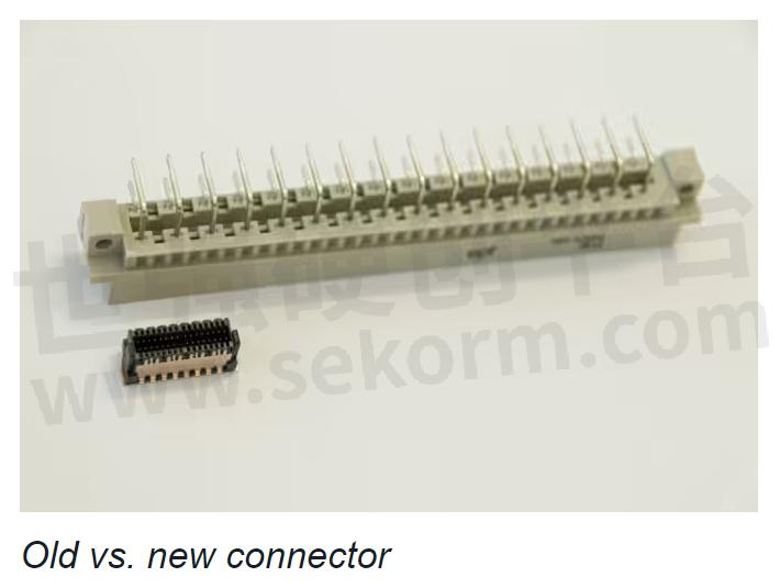
The field of modern electrical engineering is subject to one trend more than ever: miniaturization. Assemblies and their components must not only become increasingly more powerful, but they must also become increasingly smaller. Nevertheless, they are often used in harsh real-world conditions. Components as well as connectors are therefore becoming more and more delicate, while the amount of stress placed on them remains the same. However, a high-quality connector resists this stress not only as well as its older and bigger predecessor, but even better. This is due to further developments in material composition as well as in product design, such as further developments in the geometry of insulator material.
A wide range of influencing factors affects the robustness of a board-to-board connector:
Surface
Contact design
Contact system
Termination technology
Insulator material design
Tolerance range
Influencing Factor – Surface

One influencing factor is the plating. This largely determines the durability of the connector, which is usually measured in mating cycles. When used in the field, the connector is subject to certain micromovements. These lead to abrasions and, as a result, oxide formation. The consequence is an increased level of contact resistance and therefore poorer signal transmission quality.
A high-quality and durable contact coating is therefore decisive as regards surface abrasion.
Influencing Factor – Contact Design
The contacts of a PCB connector are stamped or turned using a CNC machine. When stamped, however, an inhomogeneous, sharp-edged surface that is visible under a microscope is produced on the underside of the stamped strip of material. Conventional systems make contact on this stamped edge, which entails an increased level of surface abrasion and therefore a higher degree of contact resistance.
Influencing factor – Contact System

Traditional two-piece connectors have one male contact and one female contact. However, in the event of strong shock, the male connector may lift off of the female connector. To prevent such an interruption of contact, a double-sided female connector can be used to provide redundancy and thus contact reliability, as the second female contact ensures signal transmission at all times via at least one contact point.
Influencing Factor – Termination Technology

There are several ways to attach connectors to PCBs.
One of these is to use the previously mentioned press-fit technology. The aim of this technology is to achieve the greatest possible retention forces between the connector and the PCB using the least possible amount of press-fit force. The retention forces are decisive for the mechanical connection, which in turn must withstand shock and vibration.
However, press-fit technology is not always suitable, for example, if PCBs are to be assembled on both sides, or if the minimum distance to components in the direction of force cannot be maintained. Surface-mount technology (SMT) is another way to create a reliable and durable connection between the connector and the PCB. Solder paste is used to solder the connectors onto the PCB’s specified connection surfaces: the solder pads.
Influencing Factor – Insulator Material Design

The geometry of a board-to-board connector’s insulator material also helps protect the contacts from being damaged during operation or assembly. It should be designed in such a way that the vulnerable contacts inside the connector are protected.
In addition, inclined insertion surfaces can prevent damage during assembly. They help to compensate for misalignment of the PCBs when mating in any direction. By using an additional capture range, the two connector halves can be plugged together without damage even in the event of a center or angle offset.
Influencing Factor – Tolerance Range

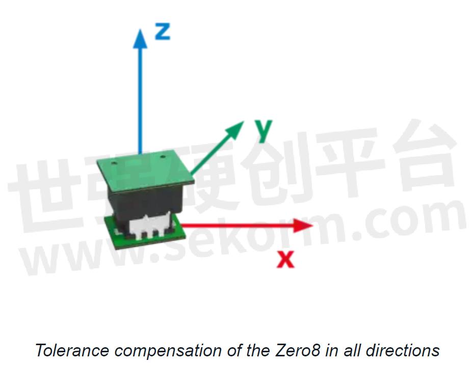
The tolerance range of a connector plays a decisive role in assessing its robustness. Mechanical movements will lead to wear or even damage to the connector if the connector cannot compensate for given tolerances.
In the field, for example, loads are generated not only in the X and Y directions, but also in the Z direction. This raises the question of whether a connector’s mating is absolutely secure. Absolutely secure mating describes the overlap area of the male and female connectors and allows not only different board-to-board distances but – depending on the size of this area – different tolerance ranges as well.
Test Methods
There are various test methods for thoroughly testing board-to-board connectors in terms of their robustness. Variables such as dielectric strength and contact resistance are each considered before and after a load test, and the condition of the contacts is inspected visually. For example, the effects of 500 mating cycles on the connector’s dielectric strength can be tested, or a climatic test can be performed to determine whether several hours at first -55℃ and then 125℃ have a negative effect on the connector’s contact resistance. When performing the temperature shock test, the connector must withstand the rapid fluctuation between these extreme temperatures 100 times for 30 minutes each. The center offset and angle offset during mating, as well as the tolerance range in the mated state, should also not only be checked in theory on the CAD model but should be extensively tested in practice, and the load capacity should be confirmed empirically. It is equally important that different tests that are of critical importance to the plating be performed in combination in order to simulate real conditions. For example, mating cycle tests and corrosive gas tests could be performed in combination to ensure that the connector’s performance in terms of contact resistance and dielectric strength has not deteriorated and that the contacts have not been damaged.
Your Design – Your Choice
There are different robustness criteria that a board-to-board connector must meet depending on the requirements of the application. For example, does it have to compensate for high tolerances? Is it subjected to large shock loads or vibrations? Is it used in environments exposed to intense heat or cold? Or does the connection solution need to be protected from moisture, corrosive gases, or dirt? If a user uses these questions as guidance when selecting their connection solution, they can be sure that their connector is perfectly equipped for use in the field.
- |
- +1 赞 0
- 收藏
- 评论 0
本文由洛希转载自ept News,原文标题为:Whitepaper: How Board-to-Board Connectors are Made Robust and Which Influencing Factors Affect the Connector,本站所有转载文章系出于传递更多信息之目的,且明确注明来源,不希望被转载的媒体或个人可与我们联系,我们将立即进行删除处理。
相关推荐
ept(依媲梯)连接器选型指南
Product Groups Overview Company Profile Colibri® connector One 27® connector DIN 41612/IEC 60603-2 connector flexilink connector VarPol connector PC/104, PC/104-Plus connector TCA Produkte connector hm2.0 connector Velox connector Power Terminals Assembly Tools & Machines Part Numbers Index
EPT - SIGNAL CONNECTORS,PC/104压接式连接器,PC/104-PLUS PIN HEADER,内六角螺钉,SOCKET STRIPS,ALIGNMENT TOOL,MODULAR CONNECTOR,PC/104 CONNECTOR,SHROUD,高速背板连接器,PCB CONNECTOR,ASSEMBLY MACHINES,IDC-FEMALE CONNECTOR,通用支持工具,HIGH SPEED SIGNAL CONNECTORS,支持工具,旋转刀架,KEYING PLUG,HIGH-SPEED BACKPLANE CONNECTORS,PC/104-PLUS母连接器,ONE27 IDC-FEMALE CONNECTOR,DIN FEMALE CONNECTOR SUPPORT TOOL,DIN公头连接器压装工具,电源插头,电源背板连接器,直销式收割台,PC/104-PLUS母连接器支持工具,PC/104-PLUS SUPPORT TOOL,信号连接器,PC/104 SUPPORT TOOL,电缆连接器,HARD METRIC CONNECTORS,MALE CONNECTOR SUPPORT TOOL,SOCKET CAP SCREW,硬度量连接器,RECEPTACLE,POWER TERMINALS,PC/104母连接器支撑工具,PRESS-FIT TOOL,产品压合工具,ANGLED PIN HEADER,DIN 41612 POWER CONNECTORS,水平PCB连接器,POTTED CONNECTORS,IDC TYPE B FEMALE CONNECTOR,OVERMOLDED CONNECTORS,PC/104 PRESS-FIT CONNECTORS,SHIELDS CABLE CONNECTORS,SOCKET CONNECTOR,DIN 41612产品压合工具,DIN FEMALE CONNECTOR EJECTOR TOOL,PIN HEADERS,高温DIN 41612连接器,薄型凹形连接器,FEMALE CONNECTOR PRESS-FIT TOOL,封装连接器,STRAIGHT PIN HEADER,DIN母头连接器支撑工具,工具适配器,DIN FEMALE CONNECTOR PRESS-FIT TOOL,电力支持工具,后配接触点,角度倾斜ONE27连接器,CUSTOMIZED CONNECTORS,CABLE CONNECTORS,POWER TERMINAL PRESS-FIT TOOL,CODING KEYS,LOCK NUT,COMPACTPCI连接器,PC/104 FEMALE CONNECTOR SUPPORT TOOL,HIGH TEMP CONNECTORS,引脚接头支撑工具,垫圈,HIGH SPEED BACKPLANE CONNECTOR,一个27英寸IDC母头连接器,电源母连接器压合工具,DIN MALE CONNECTOR INSERT BLOCK,DIN EXTRUDING TOOL SINGLE CONTACTS MALE CONNECTOR,CONNECTOR,自定义连接器,LOW PROFILE FEMALE CONNECTOR,插座和连接器,POWER FEMALE CONNECTOR,FEMALE CONNECTOR,STANDARD CONNECTOR,POWER TERMINALS PRESS-FIT TOOL,ASSEMBLY TOOLS,SIGNAL B+ SUPPORT TOOL,ROTARY TOOL HOLDER,SOCKETS CONNECTORS,PC/104-PLUS PRESS-FIT TOOL,对齐工具,PC/104-PLUS针座,快速释放刀架,DIN 41612 PRODUCTS PRESS-FIT TOOL,DIN连接器,PC/104-PLUS支持工具,PC/104-PLUS FEMALE CONNECTOR,QUICK RELEASE TOOL HOLDER,CUSTOMER SPECIFIC CONNECTORS,HIGH TEMP DIN 41612 CONNECTOR,硬公制连接器,客户特定的连接器,POWER MALE CONNECTOR SUPPORT TOOL,CABLE ASSEMBLY,DIN 41612电源连接器,DIN键控钳,动力压入配合工具,装配机,装配工具,引脚座压合工具,间隔物,POWER FEMALE CONNECTOR PRESS-FIT TOOL,MISALIGNMENT ONE27 CONNECTORS,DIN KEYING PLIERS,插座,DIN INSERTION TOOL SINGLE CONTACTS FEMALE CONNECTOR,DIN CONNECTORS,PC/104母连接器,HORZONTAL PCB CONNECTOR,电源端子支撑工具,预配合触点,电源公连接器压合工具,HIGHSPEED BACKPLANE CONNECTOR,DIN内螺纹压装工具,LOW PROFILE MALE CONNECTOR,阴接头,HIGH-SPEED AND POWER CONNECTORS,PC/104-PLUS压接式连接器,SOCKET CONNECTOR,屏蔽电缆连接器,锁紧螺帽,电源插头连接器支撑工具,FEMALE CONNECTOR SUPPORT TOOL,DIN 41612信号连接器,CONNECTOR,REPAIR KIT,IDC B型母连接器,PC/104支持工具,DIN 41612 SIGNAL CONNECTORS,BACKPLANE CONNECTOR,PIN HEADER SUPPORT TOOL,PC/104 PRESS-FIT TOOL,PIN HEADER PRESS-FIT TOOL,HARDMETRIC CONNECTORS,HIGH-SPEED CONNECTOR,装配手工具,UNIVERSAL SUPPORT TOOL,PC/104连接器,PC/104-PLUS FEMALE CONNECTOR SUPPORT TOOL,IDC母头连接器,DIN FEMALE CONNECTOR INSERT BLOCK,FEMALE CONNECTOR PIN HEADER,信号B+支持工具,DIN内螺纹连接器压装工具,MALE CONNECTORS,插座连接器,MALE CONNECTOR,TOOL ADAPTER,COMPACTPCI CONNECTORS,HORIZONTAL PRESS-FIT PCB CONNECTOR,POWER TERMINALS SUPPORT TOOL,水平压合式PCB连接器,电源端子压合工具,GUIDING BLOCK,SWITCHING CONNECTOR,POWER BACKPLANE CONNECTOR,插座条,PCB接插件,公头连接器,SMT板对板连接器,CONNECTORS,高速信号连接器,PRESS-FIT CONNECTOR,CODING PLIERS,标准连接器,母连接器支撑工具,PHILIPS SCREW,未对准ONE27连接器,编码钳,PLUG,压入配合连接器,INSERTION TOOL,电源端子,开关连接器,DIN母连接器插入块,高温连接器,母连接器引脚接头,LATE-MATING CONTACTS,PC/104-PLUS连接器,SMT BOARD-TO-BOARD CONNECTORS,POWER SUPPORT TOOL,PC/104-PLUS PRESS-FIT CONNECTORS,PRODUCTS PRESS-FIT TOOL,母连接器压合工具,公接头,高速连接器,WASHER,插头,THTR-CONNECTORS,飞利浦螺丝,PC/104压装工具,信号B+压装工具,SPACER,FEMALE CONNECTOR,围带,PC/104 FEMALE CONNECTOR,DIN挤压工具单触点公头连接器,PC/104-PLUS CONNECTOR,SUPPORT TOOL,SIGNAL B+ PRESS-FIT TOOL,包覆成型连接器,PC/104-PLUS压合工具,压入配合工具,DIN FEMALE PRESS-FIT TOOL,POWER CONNECTORS,冲压端子引脚连接器,STAMPED TERMINAL PINS CONNECTORS,FEMALE CONNECTORS,DIN公头连接器插入块,POWER PRESS-FIT TOOL,钉头,THTR-连接器,POWER MALE CONNECTOR,高速和电源连接器,DIN MALE CONNECTOR PRESS-FIT TOOL,POWER MALE CONNECTOR PRESS-FIT TOOL,DIN 41612 CONNECTOR,角形引脚排针,ANGULAR INCLINATION ONE27 CONNECTORS,连接器,电源母连接器,PRE-MATING CONTACTS,钥匙塞,模块化连接器,电源连接器,MALE CONNECTOR PRESS-FIT TOOL,HIGH-SPEED BACKPLANE-CONNECTOR,116-60074,243-62310-15,246-21000-15,971-NN022-22,962-40322-03,103-80004TH,401-51701-51,243-22360-15F,102-80025,244-31300-15,115-90065,401-55101-51,991-500700-11,243-63360-15F,264-61303-12,911-32046,911-322XX,911-32044,971-NN010-31,404-61NN-LLL-440-1,308-50100-42,308-50100-41,404-53016-51,115-79055,304-40054-02TH,115-79056,101-65005,243-5722-4/1,401-51501-51VP1,102-90064,102-90066,109-40024TH,112-40084,244-41000-15,404-52068-51,102-90065,243-11360-15F,124-60062-00,124-60062-02,404-52012-51,972-NN018-31,115-90064,104-65016-03,306-65069-14,104-65016-01,104-65016-02,243-21020-15,124-60142-00,243-22311-15,115-80065TH,102-90075,402-51501-51VP1,115-40074TH,884-046-W1,890-701-W25,243-41310-15,890-701-W22,972-NN018-21,104-60464-01,102-80075,104-60464-02,886-900-W1,886-900-W3,108-60054,886-900-W5,972-NN021-22,117-X,108-40044,108-40046,112-40064,102-80064TH,972-NN053-22,115-15408,971-NN012-21,104-60464-03,124-40112-00,972-NN018-YX,112-40066,890-701-W19,104-19003,112-40065,115-65065,102-80066,115-65066,102-80065,102-80064,101-65015,115-15402,108-60065,403-53040-51,911-320XX,115-15401,108-40034,108-40036,115-15405,403-52050-51,112-66065,102-63024-01,102-63024-02,404-51020-51,102-63024-03,403-51080-51,243-5619-2/1,111-40264,886-462-XX,991-501500-11,116-60054,115-90014,115-90015,243-5722-2/1,244-23300-15,892-405,892-404,892-403,892-402,108-40024,892-401,108-40025,246-11300-15,892-400,244-11600-1,108-60084,243-5625-4/1,890-058-W1,108-40015,104-40075,244-62000-15,304-90066-03,404-61NN-LLL-100-1,108-40014,116-80064TH,102-69004-03,104-65566-02,890-713-W11/1,102-69004-02,104-65566-01,104-65566-03,971-NN012-31,308-61013,401-55101-51VP1,402-51401-51,102-69004-01,982-NN011-31,890-711-W25/1,972-NN011-21,124-40122-00,104-40046,108-60015,104-40044,115-40065TH,302-65066-04,404-52020-51,116-69054,308-62113,115-60014,962-40NN2-12,244-61300-15,402-51301-51,404-52032-51,892-210,115-90015TH,115-69064,108-60025,304-79066-03,404-61NN-LLL-120-1,124-60042-02,884-X,115-40054TH,103-40064,308-62123,103-40065,124-60042-00,890-710-W25,910-6XXXX,103-69064,962-40NN2-03,886-466-XX,892-200,124-60162-00,910-20015,884-201,244-X,884-202,102-68014-01,884-200,102-68014-03,115-60044,102-68014-02,103-60014,304-65066-04,110-60025,110-60024,404-51032-51,892-202,892-203,116-40034TH,104-40016,243-5625-2/1,910-20020,403-53068-51,403-52080-51,982-NN011-21,884-453,884-451,108-60044,110-60015,110-60014,243-5525-1/1,890-051-W1,116-69064,884-713-W111,404-51068-51,243-5725-2/1,890-711-W25,991-X,308-50102-41,104-49054,308-50102-42,971-NN026-21,103-40034,103-40035,116-40054TH,103-60044,102-65025-02,102-65025-01,102-65025-03,245-31010-15,264-60303-12,104-49064,911-32244,104-69004-01,104-69004-02,512-22170-453,104-XXXXX-02,104-69004-03,104-XXXXX-01,104-40014,103-40024,103-90004TH,890-330-XX,103-40025,103-60054,104-XXXXX-03,103-40024TH,119-90064,102-90005TH,119-90065,110-60064,884-401,116-80064,116-90064,264-61303-02,972-NN023-22,090-X,115-69054,304-90064-05,110-60065,304-90064-02,103-40014,103-60064,304-90064-01,103-40015,911-32006,911-32004,911-32246,244-8014,304-40064-02TH,244-8013,244-8012,304-65056-04,244-8011,115-79065,115-79066,264-60303-02,886-601-1,890-710-W25/1,972-NN011-31,102-49064,971-NN026-31,102-80005TH,115-80064,115-80065,243-21010-15,244-8021,884-406,890-336,971-NN051-22,890-331,890-720-W25,404-53068-51,115-40046TH,890-334,890-335,890-332,890-333,890-720-W22,103-90165,103-68004,991-501000-11,243-5719-2/1,512-50501-163,102-40026,886-900,102-40024,910-22020,244-8034,244-8033,981-NN011-21,244-8032,244-8031,243-5511-1/1,244-11300-15,243-5622-4/1,315-15401,243-31320-15,890-348,972-NN013-31,972-NN011-YX,116-90054,315-15402,104-65045-01,104-65045-02,104-65045-03,101-40024TH,115-40035TH,103-68014,884-712-W125,910-22015,981-NN011-31,244-8041,890-317,403-53012-51,972-NN013-21,308-X,403-52032-51,886-115-W21,304-80016-03,304-68014-02,107-40064,107-40066,882-201,107-40065,102-40044,404-51012-51,243-5525-5/1,961-60NN6-12,890-720-W19,404-61NN-LLL-140-1,403-51050-51,302-63064-02,890-720-W11,102-90065TH,961-60NN6-17,123-40181-00,512-50500-163,936-66NN5,982-NN010-21,936-66NN4,884-261,884-262,304-78116-04,884-260,304-40064-05TH,243-5719-4/1,109-40014,109-40015,245-21010-15,401-55601-51,243-5622-2/1,982-NN010-31,110-61084,243-63010-15,304-40065-03,971-NN006-21,102-40074,109-40024,404-53012-51,404-59016-61,109-40025,116-90064TH,113-40160,243-5725-5/1,404-59026-61,107-40016,124-88122-00,123-40121-00,264-17302,971-NN018-21,107-40015,107-40014,991-500600-11,115-40026TH,890-720-W47,403-53050-51,971-NN006-31,244-21600-1,981-NN013-21,244-61000-15,244-11000-15,962-17NN2/1,401-51201-51,105-40064,308-51100-41,105-40066,107-40024,403-51040-51,107-40026,107-40025,115-40015TH,884-252,884-250,884-251,304-90064-02TH,243-5525-3/1,308-51100-42,890-602-W5,101-80004TH,890-602-W1,302-40064-05TH,981-NN013-31,244-63000-15,304-78106-04,403-52040-51,102-79166-01,109-40064,102-79166-03,102-79166-02,304-80014-01,112-61084,304-80014-02,244-51000,304-80014-05,117-40164,243-5511-5/1,103-40064TH,971-NN018-,INDUSTRIAL PC,医学,建筑技术,底板,POWER BACKPLANE,军事的,CRANE TECHNOLOGY,MEDICAL TECHNOLOGY,农业工程,POWER SUPPLY,DATACOM,电力应用,AEROSPACE,OARD-TO-BOARD APPLICATIONS,背板系统,科技医疗,高速应用,电源背板,MEASURING TECHNOLOGY,MILITARY,PLUG-IN CARD,机床,BASE BOARD,子车,嵌入式PC模块,AUTOMOTIVE ELECTRONICS,DATACOM,起重机技术,POWER MODULE,PCB CHAINING,AGRICULTURE ENGINEERING,RUGGEDIZED SYSTEMS,MEDICAL TECHNOLOGY,DAUGHTERCARD,仪表,PC-COMPATIBLE MODULES,IDC连接,内部逻辑,MEDICAL,BACKPLANE-SYSTEMS,AUTOMOTIVE,INTRALOGISTICS,CONSUMER ELECTRONICS,IDC-CONNECTION,电信,TRANSPORTATION,消费电子,BACKPLANE,航空航天,DATACOM,INSTRUMENTATION,无线通讯,测量技术,航空电子,TELECOMMUNICATIONS,PCB链接,BACKPLANE-DAUGHTERCARDS,背板间,POS-SYSTEMS,功率模块,交通运输,推进技术,TELECOM,PROPULSION TECHNOLOGY,游戏,工业PC,MILITARY,INDUSTRIAL AUTOMATION,POS系统,网络系统,PC兼容模块,HIGH SPEED APPLICATIONS,板对板应用,BUILDING TECHNOLOGY,LED,AVIONICS,TELECOM,BOARD-TO-BOARD APPLICATIONS,发光二极管,工业自动化,工控机,EMBEDDED PC MODULES,电源,POWER APPLICATIONS,MACHINE TOOLS,NETWORK SYSTEMS,AEROSPACE,加固系统,GAMING,IPC,汽车电子,插件卡,COMPACTPCI
Rosenberger Hochfrequenztechnik GmbH & Co. KG and ept GmbH Develop automotive Hybrid Connectors
The cooperation between ept and Rosenberger integrates both types in combined hybrid connectors which can be assembled on the printed circuit board using either conventional soldering technology or the advantageous press-fit technology.
ept Introduced Colibri 25+ Gbps High-Speed Connectors: Sample and S-parameters Access at Embedded World 2024
ept has succeeded in developing a high-speed connector with the Colibri 25+ Gbps that is not only compatible with PCI Express Gen4, but also enables excellent signal quality and is therefore a better alternative to the more interference-prone USB 4.0. ept will be offering samples and S-parameters of the Colibri to interested parties at embedded world 2024 in Nuremberg.
高达25+Gbps的Colibri®高速连接器
Colibri®高速连接器,支持高达25 Gbps的数据传输速率,适用于高数据传输率的应用。该连接器系统具有0.5 mm的间距,提供多种速度和引脚数量选项,特别适用于COM Express®应用。Colibri®连接器具有抗扭转保护、高密度信号引脚、EMC屏蔽和板锁定等特性,确保信号完整性和连接的可靠性。产品适用于多种行业,包括工业自动化、医疗保健、测量和交通技术以及汽车电子。
EPT - 屏蔽式两排SMT连接器,高速连接器,HIGH-SPEED CONNECTOR,SHIELDED, TWO-ROW SMT CONNECTOR,401-51303-51,401-55501-51,401-55503-51,401-51703-51,401-55303-51,401-51403-51,402-51501-51,401-55301-51,401-51701-51,401-51401-51,401-55601-51,401-55104-51,401-51101-51,401-51103-51,401-55603-51,402-51301-51,401-55101-51,401-55401-51,401-55103-51,401-55701-51,402-51601-51,401-55403-51,XXX-XXXXX-XXVP1,401-55703-51,401-51501-51,401-51503-51,402-51101-51,401-51301-51,402-51701-51,401-51603-51,402-51401-51,401-51601-51,401-51104-51,INDUSTRIAL AUTOMATION,DATACOM,HEALTHCARE TECHNOLOGY,信息娱乐,测量,GAMING,医疗技术,销售点,工业自动化,MEASUREMENT,游戏,INFOTAINMENT,POINT OF SALE
962-40326-03 PC/104母连接器,产品数据表
本资料为ept GmbH生产的PC/104型母座连接器产品数据表。该连接器具有64个触点,采用焊接端接技术,适用于PC/104性能等级2标准。其主要特性包括:接触电阻小于20毫欧姆,绝缘电阻大于10^6兆欧姆,操作电流最大1.9安培,操作电压150伏特,工作温度范围为-55°C至+125°C。
EPT - PC/104 FEMALE CONNECTORS,PC/104母连接器,962-40326-03
961-60NN2-12 Varpol母连接器单排,产品数据表
本资料为VarPol单排母座连接器(型号:961-60nn2-12)的技术规格说明书。该连接器采用压接式端子技术,适用于多种电路板材料,具有多种性能指标和电气参数。
EPT - VARPOL母头连接器,VARPOL FEMALE CONNECTOR,961-60NN2-12
962-40206-03 PC/104母连接器,产品数据表
本资料为ept GmbH生产的PC/104型female连接器产品数据表。该连接器具有40个触点,采用焊接端接技术,适用于高性能级2的PC/104接口。其规格包括最大操作电流1.9A、操作电压150V,接触电阻小于20mΩ,绝缘电阻大于106MΩ。材料方面,绝缘体为PBT玻璃填充,符合UL 94 V-0标准;接触材料为铜合金。此外,提供多种3D格式下载。
EPT - PC/104 FEMALE CONNECTORS,PC/104母连接器,962-40206-03
961-60NN2-07 Varpol母连接器单排,产品数据表
本资料为VarPol单排母座连接器(型号:961-60nn2-07)的产品数据表。该连接器采用压接式终止技术,适用于多种电子设备,具有高性能水平、宽工作温度范围和良好的电气特性。
EPT - VARPOL母头连接器,VARPOL FEMALE CONNECTOR,961-60NN2-07
Zero8 Connectors Board-to-Board Distances from 6.00 mm to 21.00 mm, Able to Withstand at Least 500 Mating Cycles
The Zero8 product family from ept has been specially developed for demanding industrial applications and offers maximum scalability: You can adapt types, stack heights, and pin counts to suit your individual requirements. The socket and plug are currently available as mid-profile and low-profile types and will also be available as high-profile and angled versions in the future. Due to the different heights, Zero8 connectors can be used to achieve board-to-board distances from 6.00 mm to 21.00 mm – a variable number of pins (between 12 and 80) can be requested.But that’s not all.
961-60NN2-03 Varpol母连接器单排,产品数据表
该资料为VarPol单排母座连接器(型号:961-60nn2-03)的产品数据表。介绍了其技术规格、材料、机械特性、电气特性和孔位规格等详细信息。
EPT - VARPOL母头连接器,VARPOL FEMALE CONNECTOR,961-60NN2-03
243-11321-15 HM2.0公头连接器A型客户图纸
这份资料是一份元器件的引脚排列和封装设计文档,详细列出了元器件的引脚编号、类型和尺寸信息。文档中包含了元器件的详细引脚排列图,以及相关的尺寸和标注。资料中未提及具体品牌或公司信息。
EPT - MALE CONNECTOR,公接头,243-11XXX-15,243-XXXXX-05,243-11321-15
961-40NN6-12 Varpol母连接器单排,产品数据表
本资料为VarPol单排母座连接器(型号:961-40nn6-12)的产品数据表。该连接器具有多种规格,接触点数量从2到36不等,适用于高性能电子设备。
EPT - VARPOL母头连接器,VARPOL FEMALE CONNECTOR,961-40NN6-12
电子商城
现货市场


登录 | 立即注册
提交评论