What Is a DC/DC Converter? Part 4


Hello, everyone, in this volume, I will compare and explain the features of synchronous and nonsynchronous (diode) rectification methods of DC/DC Converters.
As a function of DC/DC converters, the actual historical order is as follows:
nonsynchronous (diode) rectification
→ synchronous rectification with reverse current protection (normal PWM)
→ synchronous rectification without reverse current protection (forced PWM).
To simplify synchronous rectification and highlight its features, I dare to start with explanation of DC/DC converters without reverse current protection, which is forced PWM. Later, I will also explain the loss factors which make efficiency of DC/DC converters worse.
Contents
DC/DC Converters' Rectification Method
Comparison of Synchronous and Nonsynchronous Rectification in Buck DC/DC converters
Comparison of Operation at Light Loads
Comparison of Efficiency between Actual Synchronous and Nonsynchronous Rectification
Improvement in Efficiency of Synchronous Rectification at Light Load by Adding a Reverse Current Protection Function
High-frequency Noise Generated by Discontinuous Conduction Mode due to Reverse Current Protection
Efficiency Loss of DC/DC Converters
DC/DC Converters' Variation
Conclusion
DC/DC Converters' Rectification Method
Previously, I explained two switches (SW), such as,
(1) SW S1 connected between input voltage and the inductor to store energy in the inductor, and
(2) SW S2 to release the stored energy,
and how these two SWs are alternately switched to generate the voltage required by the load. Now, this is the mainstream of rectification method, which is called synchronous rectification. On the other hand, there is a conventional method that uses a diode instead of SW S2, which turns on during the period when the inductor releases its energy. This method is called diode rectification or nonsynchronous rectification.
Let me explain synchronous and nonsynchronous (diode) rectification method with PWM control buck DC/DC converters as an example.
Comparison of Synchronous and Nonsynchronous Rectification in Buck DC/DC Converters
Figure 1 shows the configuration of nonsynchronous (diode) buck DC/DC converters and synchronous buck DC/DC converters.
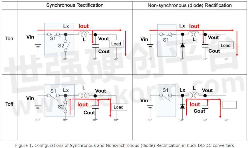
Both synchronous and nonsynchronous rectification have the same configuration of the high-side SW, S1, which turns on during the Ton period.
In synchronous rectification, the low-side SW, S2, is controlled to turn on as soon as the high-side SW, S1, turns OFF after the Ton period ends. The inductor tries to continue to flow the current, therefore, the inductor current is supplied from the GND through the low-side SW.
On the other hand, in nonsynchronous (diode) rectification, during the period when the high-side SW is on, the voltage of the Lx node becomes Vin, and the diode is not conductive because of the reverse biased voltage. Even if the high-side SW turns off, the inductor continues to flow the current, therefore, the energy of the Lx node in Figure 1 is continuously discharged to the output. Because of the drastic drop of the Lx node voltage to being lower than the GND level, the forward current begins to flow through the diode, and the inductor current is supplied from the GND.
Comparison of Operation at Light Loads
As shown in Figures 2(1) and 2(2), when the load current is more than 1/2 of the inductor ripple current, both synchronous and nonsynchronous (diode) rectification are equal in operation. However, if the load current is less than 1/2 of the ripple current, the operation is different.
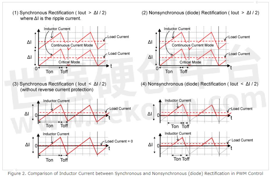
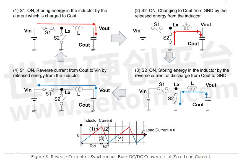
In the synchronous rectifier without a reverse current protection circuit, as shown in Figure 2(3), even if the load current becomes less than 1/2 of the ripple current, the operation does not change while maintaining the time ratio of Ton and Toff. Therefore, the inductor current becomes negative if the load current becomes less than half of the ripple current. In other words, the current from Vout to GND continues to increase, and the inductor stores energy because of this reverse current. Even if the low-side SW turns off and the high-side SW turns on, the inductor tries to continuously flow the reverse current. Therefore, the current flows in reverse from Vout to Vin through the inductor until the energy stored by the current flowing from Vout to GND becomes zero. This is shown in Figure 3.
Consider the case of zero load current as shown in Figure 3. In this case, after all the current supplied from Vin and GND is stored in the output capacitor Cout, the same intensity of current flows in reverse from Cout to GND and Vin. In other words, all current supplied by Vin is returned to Vin, therefore, it shows that there is no loss of energy in an ideal circuit even if the inductor current flows in reverse.
Because synchronous rectification without reverse current protection allows reverse current to operate continuously over the entire range of load current, the output voltage, Vout, is expressed as:
Vout = Vin × Ton / (Ton + Toff).
On the other hand, in nonsynchronous (diode) rectification, as shown in Figure 2(4), because the diode does not allow a flow of the inductor current in reverse, both the high-side SW, S1, and the diode turn off, and there is a period when the current is zero. This is called discontinuous conduction mode (DCM). In the discontinuous conduction mode, time ratio control is not possible.
Comparison of Efficiency between Actual Synchronous and Nonsynchronous Rectification
As I explained so far based on ideal SWs and ideal diodes, both have 100% efficiency. From here, I would like to compare the efficiency of synchronous and nonsynchronous rectification with actual SWs and diodes.
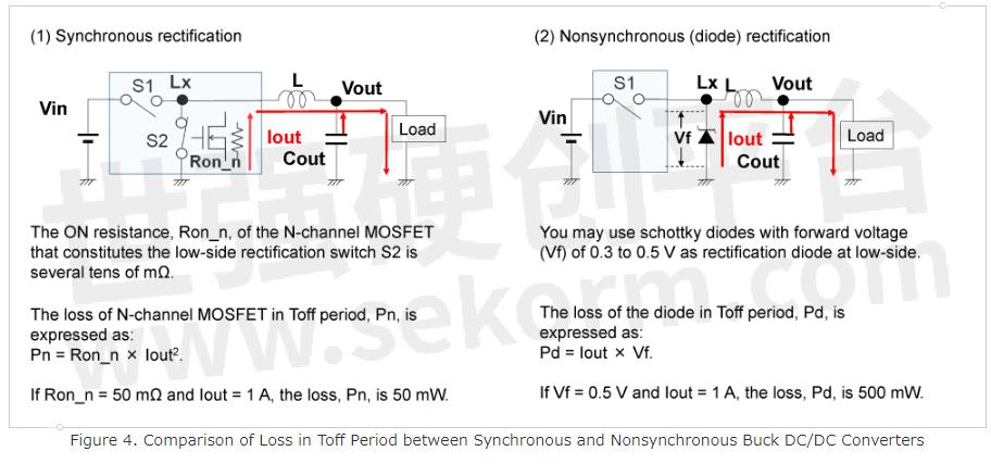
As shown in Figure 4(1), MOSFETs are generally used for SWs. The on-resistance of MOSFET, which means the resistance of MOSFET in a conductive state, used in DC/DC converters is generally less than a few tens or few hundreds of mΩ. (The larger the MOSFET size is, the lower the on-resistance is.)
On the other hand, as shown in Figure 4(2), a Schottky barrier diode, which has a relatively small forward voltage Vf, is used in the nonsynchronous converter. The Vf voltage of the Schottky barrier diode is generally in the range of 0.3V to 0.5V.
Let us calculate and compare the losses in the case of 1A load current, where the on-resistance of the low-side SW, S2, for synchronous rectification, is 50mΩ, and the Vf of the nonsynchronous rectification diode, D1, is 0.5V, respectively. The losses of synchronous and nonsynchronous rectification are equivalent at Ton, so let's compare the losses at Toff.
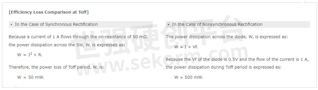
In these cases, the loss during the Toff period of nonsynchronous (diode) rectification is an order of magnitude larger than that of synchronous rectification.
The nonsynchronous (diode) rectification method has the advantage of simplifying the design of control circuits in DC/DC converters because it only requires control of SW S1 to store energy in the inductor. Therefore, it has been widely used. However, the voltage supplied by DC/DC converters is becoming lower as LSIs such as CPUs become finer and more integrated. This means that the Toff period becomes longer when the input voltage to the DC/DC converter is assumed to be constant. In other words, the output current flows through the rectification diode for a longer period, so the loss due to the Vf voltage of the rectification diode can no longer be ignored, as shown in the previous calculation. For this reason, synchronous DC/DC converters have become the mainstream.
Improvement in Efficiency of Synchronous Rectification at Light Load by Adding a Reverse Current Protection Function
In synchronous rectification, when the load current is smaller than half of the ripple current, the inductor current flows in reverse. This reverse current flowing through the resistive component of the high-side and low-side MOSFET SW causes loss. This is one of the factors that reduces the efficiency of synchronous rectification at light loads. A DC/DC converter with an added reverse current protection function, which turns off the low-side MOSFET when detecting reverse current, reduces this loss.
If the reverse current of low-side is prevented, storing energy in the inductor by reverse current does not occur, and thus reverse current to the high-side to release the stored energy does not occur either. To prevent the reverse current, turn-off control is only required for low-side SW.
By adding a reverse current protection function, the operation of synchronous DC/DC converters at light load is equivalent to that of nonsynchronous (diode) DC/DC converters.
Note: PWM Control with or without Reverse Current Protection
The operation of synchronous DC/DC converters with PWM control differs depending on “with” and “without” reverse current protection. In general, the case of “with” reverse current protection which operates in a similar way to nonsynchronous (diode) rectification is designated as "normal PWM." The case of “without” reverse current protection is designated as "forced PWM."
High-frequency Noise Generated by Discontinuous Conduction Mode due to Reverse Current Protection
In synchronous DC/DC converters without reverse current protection (Forced PWM), the inductor current flows in reverse when the load current falls below the average value of the inductor ripple current (= half of the ripple current) at light loads. The inductor current flows continuously and the PWM operation, which regulates the output voltage by the time ratio, can be maintained as in the case of heavy load. The inductor current continuously flows in this case and this operation is called the continuous conduction mode (CCM). Figure 5(1) shows an image of the operation waveform of the Lx node and inductor current in this case.

On the other hand, when the reverse current protection function is activated, the low-side SW turns off at the moment when the inductor current begins to flow in reverse. As a result, the period of zero inductor current continues. This operation is called discontinuous conduction mode (DCM). When the supply path of the inductor current at the Lx node is interrupted, LC oscillation (ringing) occurs at the Lx node due to energy stored in the inductor and parasitic capacitance as shown in Figure 5(2). Thus, this results in high-frequency noise.
Efficiency Loss of DC/DC Converters
I mentioned briefly about loss of synchronous rectification and nonsynchronous (diode) rectification, here, I also explain the factors of loss in general DC/DC converters.
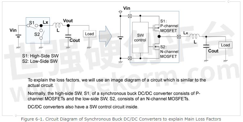
The efficiency of ideal DC/DC converters is 100%, but actual DC/DC converters have several loss factors that make efficiency worse. Losses can be roughly classified into two types: DC loss due to the load current Iout, flowing through the resistive component of the circuit, and AC loss due to the switching operation of DC/DC converters. I will explain the main loss factors in synchronous buck DC/DC converters here. So far, we have shown DC/DC converters using only a simple SWs' diagram. Now, please look at Figure 6-1 which shows the real circuit elements to explain the loss factors. The high-side SW is replaced by a P-channel MOSFET and the low-side SW by an N-channel MOSFET, and a SW control circuit is added.
(1) DC Loss
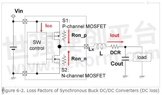
There is a loss caused by the load current Iout, flowing through the resistive component of the SWs and the direct current resistive (DCR) components of the inductor during the Ton and Toff periods. There is power loss consumed by the control circuit. These losses fall into this category. Figure 6-2 shows the main DC loss factors.
1. Loss due to On-resistance of Pch/Nch MOSFET SW
The on-resistance, which means the resistance component during the conduction state, of the MOSFET as a SW is a few tens or few hundreds of mΩ. The loss during the Ton period occurred due to on-resistance, Ron_p, and Iout of P-channel MOSFET SW, and the loss during the Toff period occurred due to on-resistance and Iout of N-channel MOSFET SW. The loss during the Ton and Toff periods are expressed as:
Pon = Ron_p × Iout2 × Ton / T, and
Poff = Ron_n × Iout2 × Toff / T,
where T is the period of PWM operation.
2. Loss due to Direct Current Resistance (DCR) of Inductors
Because the load current, Iout, flows continuously through the DCR of the inductor in continuous conduction mode of PWM operation, the loss, Pdcr, is expressed as:
Pdcr = Rdcr × Iout2.
3. Loss due to Power Consumed by the Control Circuit
In the PWM control method, because the SW control circuit is continuously operating, the loss, Picc, is generated due to the current consumption, Icc, of the SW control circuit.
Picc = Icc × Vin.
Because this loss is constant regardless of Iout, it is one of the factors that makes efficiency worse at light load.
(2) AC Loss
This loss occurs during SW switching. Therefore, it is also called switching loss. Figure 6-3 illustrates the main AC loss factors.
1. Loss due to Charge/Discharge of Gate Capacitance of P-channel / N-channel MOSFET SW
Turning on and off of MOSFET SW is controlled by changing the gate voltage between 0V and Vin level through charging and discharging the gate capacitance of the MOSFET. In one cycle of PWM operation, the electrical charge which is charged and discharged at the gate capacitances of the MOSFET SW, Cg_p, and Cg_n, is expressed as:
Q = (Cg_p + Cg_n) × Vin.
Because the total amount of charge consumed per second corresponds to the consumption current, the power consumption (loss), Pgate, due to charging and discharging of gate capacitance is expressed as:
Pgate = (Cg_p + Cg_n) × Vin2 × Fsw,
where Fsw is the oscillation frequency for PWM operation.
*In PWM control, this loss is constant regardless of Iout, therefore, this is one of the factors contributing to efficiency loss at light load. This loss may be included in the DC loss due to the power consumption of the SW control circuit.
2. Loss due to ON/OFF Transition Time, Tr/Tf, of MOSFET SW
Loss for Tr period:
At the instant when the high-side P-channel MOSFET SW turns on, the voltage of the Lx node is 0V. Since the Iout current flows through the P-channel MOSFET SW under Vin voltage applied across both ends of it, power loss occurs. However, after Tr time, the voltage of the Lx node becomes Vin level (on-resistance of P-channel MOSFET is negligible), therefore, there is no loss. Thus, the loss for one Tr period can be calculated using the average of the voltages at both ends of P-channel MOSFET during the Tr period.
Loss for Tf period:
It can be calculated using the same idea as in the case of Tr. Therefore, the loss for the Tr and Tf periods, Ptrtf, is expressed as:
Ptrtf = 1/2 × (Tr + Tf) × Vin × Iout × Fsw.
DC/DC Converters' Variation
Specifically, there is a synchronous PWM method with a reverse current protection function to reduce DC loss in comparison with a nonsynchronous (diode) rectification method. There is also a synchronous rectification PWM method without reverse current protection for improvement of noise. In addition, the VFM(PFM) method has been added to the lineup to further improve efficiency at light load.
Nonsynchronous (diode) rectification → Synchronous PWM method with reverse current protection (improvement for DC loss)
Synchronous PWM method with reverse current protection → Synchronous PWM method without reverse current protection (improvement for noise)
Synchronous PWM method with reverse current protection → Synchronous VFM(PFM) method (improvement for AC loss)
In the What Is a DC/DC Converter? Part 3, I explained that in the VFM(PFM) control method, which is a control method to improve efficiency at light load, the noise frequency spreads to a lower frequency because the switching cycle becomes longer as the load current decreases. Furthermore, because the VFM (PFM) control method operates in discontinuous conduction mode, this method generates high-frequency noise due to ringing, immediately after current interruption.
For these reasons, different control methods for synchronous DC/DC converters are available to suit different applications, such as those that prioritize efficiency or noise suppression.
Applications where efficiency is a top priority: synchronous DC/DC converters that can switch between the VFM(PFM) method at light load and PWM with reverse current protection during the entire range of loads.
Applications where noise suppression is important: synchronous DC/DC converters that allow reversing current.
* The former is called PWM/VFM(PFM) auto-switching, and the latter is called forced PWM.
Recently, a single product that can switch between the synchronous rectification PWM/VFM auto-switching method and the forced PWM method has been developed. The synchronous rectification PWM/VFM auto-switching method focuses on high efficiency, and the forced PWM method focuses on noise suppression by allowing reverse current flow and operating in continuous conduction mode over the entire range of load currents. Products with anti-ringing measures have also been developed to suppress high-frequency noise caused by discontinuous conduction mode.
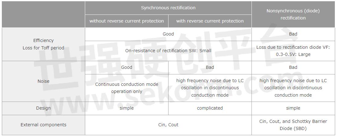
Table 1 shows the characteristics of each of the rectification methods described above.
Table 1. Comparison of Synchronous and Nonsynchronous (diode) Rectification Method
Conclusion
I would like to continue one more lesson. Next time, I will summarize what we have learned so far and that will be the last lesson about DC/DC converters.
Thank you for reading.
- |
- +1 赞 0
- 收藏
- 评论 0
本文由FY转载自NISSHINBO News,原文标题为:What Is a DC/DC Converter? Part 4,本站所有转载文章系出于传递更多信息之目的,且明确注明来源,不希望被转载的媒体或个人可与我们联系,我们将立即进行删除处理。
相关研发服务和供应服务
相关推荐

What Is a DC/DC Converter? Part 2
This time, I explained that the efficiency, which is the greatest feature of DC/DC converters, can be realized by utilizing the energy storage and release of the inductor, which is a component of DC/DC converters. We also addressed applications of linear regulators and DC/DC converters by comparing them.

What Is a DC/DC Converter? Part 5
In these five volumes on DC/DC converters, I have mainly taken non-isolated DC/DC converters as examples, and only the basics of the converters have been mentioned. As for isolated DC/DC converters, I have only explained flyback converter as an example. I would say that we are just getting to know about the fundamental concepts of DC/DC converters.

What Is a DC/DC Converter? Part 3
I explained that by connecting the power source, inductor, and switches in different ways, and by storing energy in the inductor or release from the inductor, boost DC/DC converters which make higher voltage than input voltage, or inverting DC/DC converters which make negative voltage can be implemented. I also explained the features of PWM control and VFM/PFM control as control methods.

NJW4140:用于升压/反激式转换器的MOSFET驱动开关稳压器IC
描述- NJW4140是一款适用于升压/反激转换器的MOSFET驱动开关稳压器集成电路。它具有宽输入电压范围(3V至40V),内置高效Nch MOSFET驱动电路,可提供大电流应用。具备过流保护功能,适合汽车配件、办公自动化设备、工业仪表等应用。
型号- NJW4140M,NJW4140,NJW4140R

NISSHINBO Launched 0.5A/1A 6MHz PWM/VFM Step-down DC/DC Converter RP539 Series with Synchronous Rectifier
The RP539 Series is a low-supply current CMOS-based PWM/VFM step-down DC/DC converter with a synchronous rectifier featuring 0.5A/1A output current. The RP539 Series is employing synchronous rectification for improving the efficiency of rectification by replacing diodes with built-in switching transistors.
用于升压/反激式转换器的汽车级NJW4142 MOSFET驱动开关稳压器IC
描述- NJW4142是一款适用于汽车和工业仪器的MOSFET驱动开关稳压器IC,具有宽工作电压范围(2.5V至40V),适用于升压/反激式转换器。它具备电流模式控制、外部时钟同步、PWM控制和软启动等功能,并具备过压保护、过流保护、欠压锁定和热关断等保护功能。
型号- NJW4142R-T1TE1,NJW4142R-T1,NJW4142
汽车NJW4140:用于升压/反激式转换器的MOSFET驱动开关稳压器IC
描述- 该资料介绍了汽车用NJW4140型MOSFET驱动开关稳压器集成电路。它适用于宽输入电压范围(3V至40V)的升压/反激式转换器,内置高效N沟道MOSFET驱动电路,可提供大电流应用。具有PWM控制、宽振荡频率、过流保护和欠压锁定等功能。
型号- NJW4140R-Z2(TE1),NJW4140

用于升压/反激式转换器的NJW4142 MOSFET驱动开关稳压器IC
描述- 该资料详细介绍了NJW4142是一款适用于升压/反激转换器的MOSFET驱动开关稳压器IC。它具有宽工作电压范围(2.5V至40V)、电流模式控制、外部时钟同步等功能,适用于工业仪器、消费电子等领域。
型号- NJW4142RTE1,NJW4142,NJW4142R
R1210Nxx1x系列PWM升压型DC/DC变换器
描述- 该资料介绍了R1210Nxx1x系列CMOS型PWM升压DC/DC转换器。这些转换器具有高精度、低供电电流的特点,由振荡器、PWM电路、参考电压单元、误差放大器、相补偿电路、电压检测电阻、芯片使能电路组成。此外,还包括负载瞬态控制器、低导通电阻的控制晶体管、‘LX开关’以及LX开关和输出电压保护电路。该系列IC可以仅用三个外部组件(电感、二极管和电容)构成一个低纹波、高效升压DC/DC转换器。
型号- R1210N,R1210NXX1∗-TR-FE,R1210N601C,R1210N501C,R1210N601D,R1210N501D,R1210NXX1X,R1210N301X,R1210N221D,R1210N221A,R1210NXX1A,R1210N301D,R1210N301C,R1210NXX1*-TR-FE,R1210N301A
R1286K系列2通道用于AMOLED/LCD的同步整流PWM升压/逆变DC/DC转换器
描述- 该资料介绍了R1286K系列双通道PWM升压/反激式DC/DC转换器,适用于AMOLED和LCD显示屏电源。它包含一个升压DC/DC转换器和一个反激式DC/DC转换器,可提供高达4.6V至5.8V的可选输出电压,以及-2.0V至-6.0V的负电压。具有高效率、内部启动序列控制、软启动操作、自动放电功能、短路保护和过温保护等特点。
型号- R1286K111M,R1286K010E,R1286K002J,R1286K103M,R1286K,R1286K107C,R1286K109F,R1286K004A,R1286K008E,R1286K1XXX,R1286K002E,R1286K103G,R1286K$XX*-TR,R1286K002A,R1286K006F,R1286K SERIES,R1286KXXXN,R1286KX05A,R1286KXXXX,R1286KX02X,R1286KXXXD,R1286KXXXE,R1286K005A,R1286K007C,R1286KXXXB,R1286KXXXC,R1286K009F,R1286KX02A,R1286KXXXA,R1286K0XXX,R1286KXXXL,R1286KXXXM,R1286KXXXJ,R1286K003G,R1286KXXXK,R1286KXXXH,R1286KXXXF,R1286K001B,R1286KXXXG
NJS6318 S波段二极管限幅器
描述- NJS6318是一款专为雷达系统高功率限流设计的二极管限流器。该器件可在3.00GHz至3.10GHz的频率范围内工作,具有小型化设计,无需外部触发和偏置。资料中提供了该器件的绝对最大额定值、电气特性、脉冲宽度依赖的连续额定值以及外形尺寸。
型号- NJS6318

NISSHINBO‘s 600nA Low Quiescent Current Boost DC/DC Converter for Energy Harvester
NISSHINBO‘s R1810 Series is a boost DC/DC converter for electrical power storage devices, specially dedicated to 1 cell photovoltaic energy harvester since the start-up voltage is Typ. 0.35V.This product can start up with only 9µW and is applicable for charging 1 cell photovoltaic element.
RN5RK系列VFM升压型DC/DC变换器
描述- 该资料介绍了RN5RK系列升压DC/DC转换器IC的特性、应用和电气特性。这些芯片基于CMOS技术,具有超低供电电流和高输出电压精度。它们适用于电池供电设备、相机、摄像机、录像机和手持通信设备的电源。
型号- RN5RKXX1X,RN5RKXX1A SERIES,RN5RKXX1B SERIES,RN5RK502A,RN5RK501A,RN5RK501B,RN5RK301A,RN5RKXX*$-TR-FE,RN5RK302A,RN5RK SERIES,RN5RKXX2A SERIES,RN5RK,RN5RK301B,RN5RKXX2A,RN5RKXX1A,RN5RKXX1B
用于升压/反激式转换器的NJW1871 MOSFET驱动开关稳压器IC
描述- NJW1871是一款适用于升压/反激转换器的MOSFET驱动开关稳压器IC,具有宽工作电压范围(2.5V至40V),内部Nch MOSFET驱动电路提供高效驱动,适用于高输出电流应用。该产品具备PWM控制、过压保护、过流保护、软启动等功能,适用于工业仪器等消费电子产品。
型号- NJW1871,NJW1871R,NJW1871RTE1

电子商城

现货市场


服务
可根据用户的MOSFET管进行参数检测出具报告,静态参数最大电压:7500V、检测最大电流6000A;动态参数最大电压:3300V、检测最大电流:4500A。该测试标准满足GB、IEC及行业标准等,具备可靠性评估及老化实验能力。
实验室地址: 西安 提交需求>
可定制电感最大电流100A,尺寸最小7 x 7 x 3.0mm到最大35 x 34 x 15.5 mm,工作频率100KHZ ~ 2MHZ,感值范围:0.15 ~ 100uh;支持大功率电感,扁平线电感,大电流电感,高频电感,汽车电感器,车规电感,一体成型电感等定制。
最小起订量: 5000 提交需求>
授权代理品牌:集成电路


授权代理品牌:分立元件


授权代理品牌:接插件及结构件


授权代理品牌:部件、组件及配件


授权代理品牌:电源及模块


授权代理品牌:电子材料


授权代理品牌:仪器仪表及测试配组件


授权代理品牌:电工工具及材料


授权代理品牌:机械电子元件


授权代理品牌:加工与定制


登录 | 立即注册
提交评论