OFDM Introduction

Concepts of Orthogonal Frequency Division Multiplexing (OFDM) and 802.11 WLAN
It’s important to have a fundamental understanding of Orthogonal Frequency Division Multiplexing (OFDM) because this technology is a basic building block for many of the current modulation schemes including; 802.11WLAN, 802.16 WiMAX, and 3GPP LTE. This topic discusses the basic concepts of OFDM and how OFDM is implemented in 802.11a WLAN modulation. The basic OFDM principles will be introduced using a simple analog OFDM implementation and then those concepts will be extended to the digital domain with a simple digital OFDM implementation which utilizes theFFTtransform and DSP technology. The discussion ends with an explanation of how OFDM is implemented in 802.11a WLAN and how the OFDM symbol and burst are created.
OFDM Introduction
As a technology suitable for use in mobile handsets, however, it had to wait for the development of today’s small, low-cost, low-power chipsets that can support the complex mathematics involved in the creation and demodulation of OFDM transmission. Three variants are on the horizon: the 3rd Generation Partnership Project (3GPP) standards body, which promotes the GSM family of technologies, is developing a system called Long Term Evolution (LTE). 3GPP2, which deals with cdma2000 and associated technologies, is working on Universal Mobile Broadband (UMB), while the IEEE has its 802.16 standard with its WiBro and WiMAX™ variants. All of these use OFDMA (Orthogonal Frequency Division Multiple Access) as the access methodology, bringing to OFDM support for multiple independent users and the ability to perform handovers while maintaining the link. This paper is intended to be a layer down from the details of these specific implementations and to discuss the basic OFDM technology itself as it is used in the downlink from a cell to a mobile device. The uplink has similar characteristics but the transmission is spread over multiple users. LTE, in particular, has a twist to its uplink that mixes FDMA with OFDM – Single Carrier Frequency Division Multiple Access (SC-FDMA).
In addition to new air interface technologies, the networks are being evolved to support heavy data traffic rather than just voice. They will only allow for packet access; no circuit-switched connections are possible. This means that voice must be carried over the IP network (VoIP). To support the immediacy of voice, the delays in initial access to the network and the turn-around delay typical of a packet system need to be reduced. The specific handling of real-time applications such as voice and video telephony requires specific network treatment, generally identified by the Quality of Service (QoS).
Why OFDM?
We
all learned the virtues of CDMA with the advent of the third generation
of cellular technologies. One benefit arises from having a signal that
takes a wide bandwidth to transmit. This provides better immunity to
fading as only a small portion of the energy for any one link is
typically lost due to a fade. In addition, there is fast power control
of the links to keep the noise floor as low as possible. Both of these
can be used in OFDM. The difference is in how the information is applied
to the signal. OFDM has a built-in advantage due to the way modulation
is applied at a much lower rate on each of the many sub-carriers, which,
combined with sophisticated error correction, makes it highly resistant
to the effects of fading and inter-symbol interference. It also scales
its data rates a little easier than CDMA, and allows for more advanced
antenna technology, Multiple Input-Multiple Output (MIMO) in particular.
What is OFDM?
Orthogonal Frequency Division Multiplexing (OFDM) is a digital multi-carrier modulation scheme that extends the concept of single subcarrier modulation by using multiple subcarriers within the same single channel, as shown in figure 1. Rather than transmit a high-rate stream of data with a single subcarrier, OFDM makes use of a large number of closely spaced orthogonal subcarriers that are transmitted in parallel. Each subcarrier is modulated with a conventional digital modulation scheme (such as QPSK, 16QAM, etc.) at low symbol rate. However, the combination of many subcarriers enables data rates similar to conventional single-carrier modulation schemes within equivalent bandwidths.
OFDM is based on the well-known technique of Frequency Division Multiplexing (FDM). In FDM different streams of information are mapped onto separate parallel frequency channels. Each FDM channel is separated from the others by a frequency guard band to reduce interference between adjacent channels.
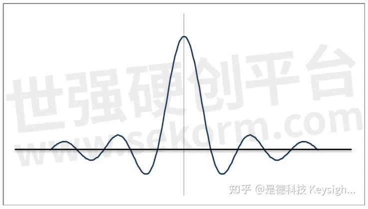
Figure 1. Spectrum of a single carrier for OFDM
OFDM is comprised of a large number of orthogonal narrow-band signals. The zero crossings occur at all multiples of subcarrier separation as shown in figure 2, so that the peak of each sub-carrier occurs at zero crossings of every other sub-carrier, making them orthogonal in the frequency domain.
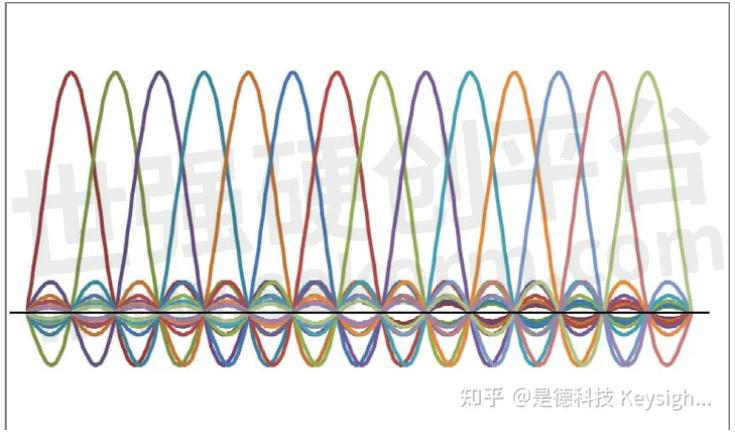
Figure 2. Spectrum of multiple OFDM sub-carriers.
Note that the extensions of the functions have been truncated in this figure.
The diagram shows each sub-carrier magnitude as 1 – in reality, this will depend on the type of modulation, which may be different for different subcarriers. Figure 3, shows groups of sub-carriers assigned to different users: those indicated with a star assigned to user 1, and those with the plus sign assigned to user 2.
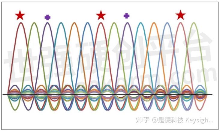
Figure 3. Two channel assignments are indicated by the star and plus sign.
It is desirable to spread the sub-carriers for each user across the whole spectrum to provide the best immunity from fading. Each particular assignment may only hold for the transmission of one symbol. Usually, there is a change of sub-carrier after each symbol, though each user will still have the same number of sub-carriers and the same modulation type on each. As well as user data, error-correcting coding is spread over all of a user’s subcarriers providing additional protection against fading. The received sub-carriers are demodulated by comparison against a reference signal (pilot) of amplitude 1 and phase 0. The reference signal for each sub-carrier must be known to allow demodulation.
OFDM signals are best described in the frequency domain as collection of sub-carriers, each with its information carried in its magnitude and phase. To transmit such a composite signal, it must be converted into the time domain. An efficient method of doing this is with an Inverse Fast Fourier Transform (IFFT). Conversely, the demodulation is performed using a FFT. All sub-carriers are extracted simultaneously, with amplitude and phase components for each one. Modulation and demodulation in most real systems are made easier by using powers of two for the number of sub-carriers.
Multipath Considerations
Let’s consider the effect of multipath signals using OFDM. Early in the development of OFDM, it was recognized that overall system performance could be improved by the addition of a guard interval between symbols. Set depending on the maximum cell size to be used in a specific system, this removes the possibility of the inter-symbol interference caused by multi-path reception over path delays up to the length of the guard interval. The guard interval (known as the cyclic prefix or CP in LTE) is a copy of the end of a symbol which is added to the beginning of the symbol. An example, of using a guard interval of ¼ for visual clarity (ie the portion of the symbol which is used as the guard interval is ¼ the length of the useful part of the symbol) is shown in Figure 4 below. Using LTE as an example of a real system, the normal guard interval length is 4.69 μs, and the symbol length is 66.7 μs, giving a 7% loss of capacity and enabling the system to cope with path delay variations up to about 1.4 km. Note that this figure represents the difference in path length due to reflections, not the size of the cell.
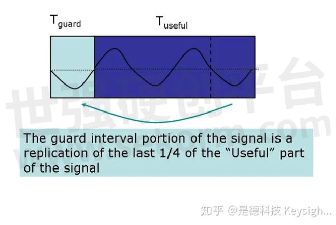
Figure 4. OFDM Guard Interval Example
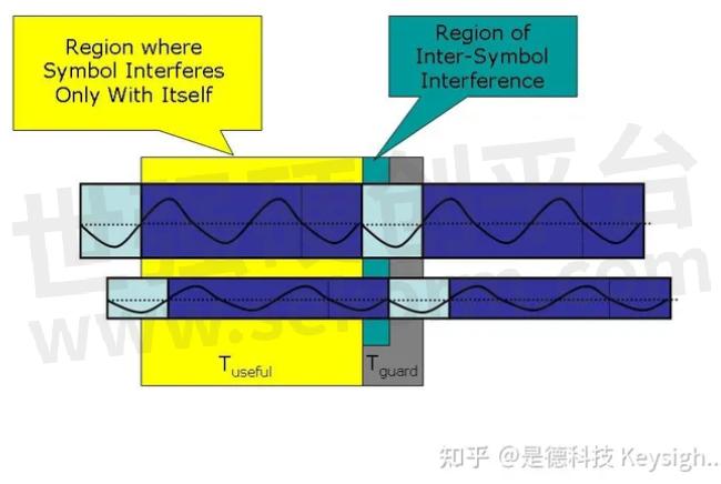
Figure 5. OFDM can eliminate ISI.
As long as the time-sampling of the symbol is within the useful part of the symbol, as shown in Figure 5, equalizers can take care of the path delay and the second path can be combined with the first to increase the probability of correct reception. Note also that, as well as a delayed signal due to multipath propagation, the second path could be from a different source – either a different antenna (diversity antenna) or a different transmitter sending the same data (as used in some single-frequency-network broadcasts).
Mitigating Near-far RF Interference
It is known that OFDM will be more difficult to operate than CDMA at the edge of cells. CDMA uses scrambling codes to protect from inter-cell interference at the cell edge whereas OFDM has no such feature. Therefore, some form of frequency planning at the cell edges will be required. Figure 6 gives one example of how this might be done. The color orange represents the entire channel bandwidth and the other colors show a plan for frequency re-use to avoid inter-cell interference at the cell edges.
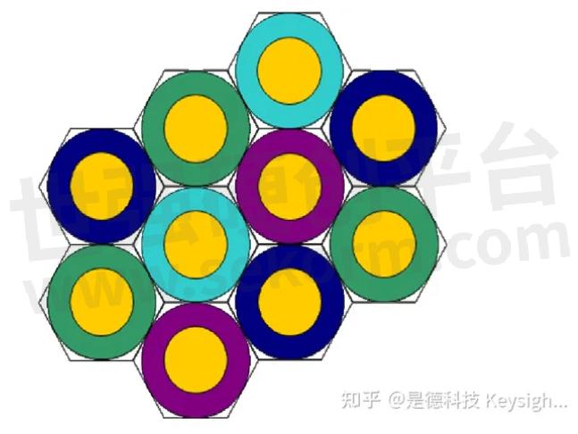
A user in the yellow bands in the center of each cell is allowed to use any of the OFDM sub-carriers. Users in the outer regions can only use a portion of the sub-carriers. The sub-carriers allowed in the outer ring of each cell have clearance from use in the outer portion of neighbor cells, reducing the interference in those sub-channels.
OFDM is based on the well-known technique of Frequency Division Multiplexing (FDM). In FDM different streams of information are mapped onto separate parallel frequency channels. Each FDM channel is separated from the others by a frequency guard band to reduce interference between adjacent channels.
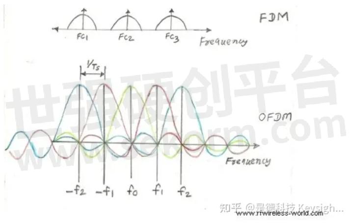
Why OFDM is better than FDM?
FDM stands for Frequency Division Multiplexing and OFDM stands for Orthogonal Frequency Division Multiplexing.
The OFDM scheme differs from traditional FDM in the following interrelated ways:
1. Multiple carriers (called subcarriers) carry the information stream,
2. The subcarriers are orthogonal to each other, and
3. A guard interval is added to each symbol to minimize the channel delay spread and intersymbol interference.
Frequency and Time Representative of an OFDM Signal
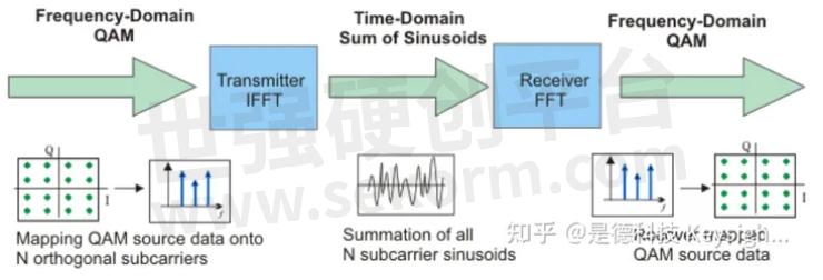
The following figure illustrates the main concepts of an OFDM signal and the inter-relationship between the frequency and time domains. In the frequency domain, multiple adjacent tones or subcarriers are each independently modulated with complex data. An Inverse FFT transform is performed on the frequency-domain subcarriers to produce the OFDM symbol in the time-domain. Then in the time domain, guard intervals are inserted between each of the symbols to prevent inter-symbol interference at the receiver caused by multi-path delay spread in the radio channel. Multiple symbols can be concatenated to create the final OFDM burst signal. At the receiver, an FFT is performed on the OFDM symbols to recover the original data bits.
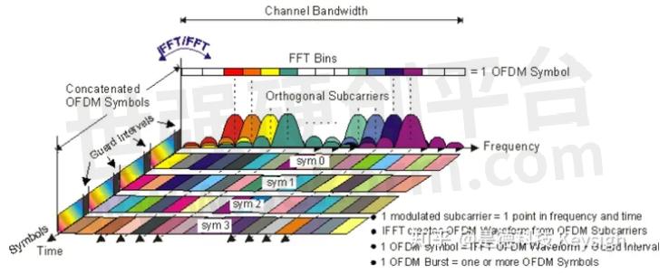
Frequency and Time Representative of an OFDM Signal
Understanding OFDM
Simple Analog OFDM System Implementation
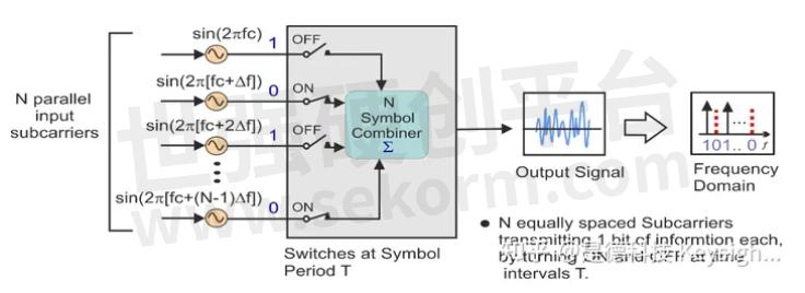
We will use a simple analog-based implementation to show the basic principles of generating an OFDM signal. In this simple OFDM system there are N sinusoidal input signals. Each subcarrier transmits one bit of information (N bits total) as indicated by its presence or absence in the output spectrum. The frequency of each subcarrier is selected to form an orthogonal signal set. These frequencies are also known at the receiver for signal recovery. Note that the output is updated at a periodic interval T that forms the symbol period. To maintain orthogonality, T must be the reciprocal of the subcarrier spacing.
Simple OFDM Generation
Understanding Orthogonality – The Importance of Orthogonally Spaced Subcarriers?
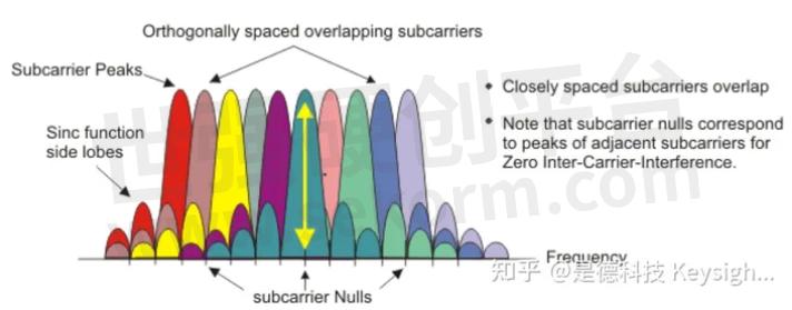
The OFDM signal can be described as a set of closely spaced FDM subcarriers. In the frequency domain, each transmitted subcarrier results in a sinc function spectrum with side lobes that produce overlapping spectra between subcarriers, see "OFDM Signal Frequency Spectra" figure below. This results in subcarrier interference except at orthogonally spaced frequencies. At orthogonal frequencies, the individual peaks of subcarriers all line up with the nulls of the other subcarriers. This overlap of spectral energy does not interfere with the system’s ability to recover the original signal. The receiver multiplies (i.e., correlates) the incoming signal by the known set of sinusoids to recover the original set of bits sent.
OFDM Signal Frequency Spectra
The use of orthogonal subcarriers allows more subcarriers per bandwidth increasing spectral efficiency. In a perfect OFDM signal, Orthogonality prevents interference between overlapping carriers. In FDM systems, any overlap in the spectrums of adjacent signals will result in interference. In OFDM systems, the subcarriers will interfere with each other only if there is a loss of orthogonality. For example, frequency error will cause the subcarrier frequencies to shift so that the spectral nulls will no longer be aligned resulting in inter-subcarrier-interference
Simple Digital OFDM system Implementation using FFT transforms
The concepts used in the simple analog OFDM
implementation can be extended to the digital domain by using a
combination of Fast Fourier Transform (FFT) and Inverse Fast Fourier
Transform (IFFT) digital signal processing.
These transforms are important from the OFDM perspective because they
can be viewed as mapping digitally modulated input data (data symbols)
onto orthogonal subcarriers. In principle, the IFFT takes
frequency-domain input data (complex numbers representing the modulated
subcarriers) and converts it to the time-domain output data (analog OFDM
symbol waveform).
In a digitally implemented OFDM system, the input bits are grouped and mapped to source data symbols that are a complex number representing the modulation constellation point (e.g., the BPSK or QAM symbols that would be present in a single subcarrier system). These complex source symbols are treated by the transmitter as though they are in the frequency domain and are the inputs to an IFFT block that transforms the data into the time domain. The IFFT takes in N source symbols at a time where N is the number of subcarriers in the system. Each of these N input symbols has a symbol period of T seconds. Recall that the output of the IFFT is N orthogonal sinusoids. These orthogonal sinusoids each have a different frequency and the lowest frequency is DC.
Simplified OFDM System Block Diagram
The input symbols are complex values representing the mapped constellation point and therefore specify both the amplitude and phase of the sinusoid for that subcarrier. The IFFT output is the summation of all N sinusoids. Thus, the IFFT block provides a simple way to modulate data onto N orthogonal subcarriers. The block of N output samples from the IFFT makes up a single OFDM symbol.
After some additional processing, the time-domain signal that results from the IFFT is transmitted across the radio channel. At the receiver, an FFT block is used to process the received signal and bring it into the frequency domain which is used to recover the original data bits.
Simple 802.11a OFDM Signal Implementation
An
802.11a OFDM carrier signal (burst type) is the sum of one or more OFDM
symbols each comprised of 52 orthogonal subcarriers, with baseband data
on each subcarrier being independently modulated using quadrature
amplitude modulation (available formats: BPSK, QPSK, 16-QAM, or 64-QAM).
This composite baseband signal is used to modulate a main RF carrier.
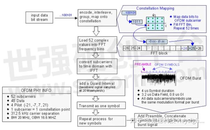
To begin the OFDM signal creation process, the input data bit stream is encoded with convolutional coding and Interleaving. Each data stream is divided into groups of "n" bits (1 bit -BPSK, 2 bits -QPSK, 4 bits -16QAM, or 6 bits -64QAM) and converted into complex numbers (I+jQ) representing the mapped constellation point. Note that the bit-rate will be different depending on the modulation format, a 64-QAM constellation (6 bits at a time) can have a bit rate of 54 Mbps while a QPSK constellation (2 bits at a time) may only have 12 Mbps.
Then 52 bins of the IFFT block are loaded. 48 bins contain the constellation points which are mapped into frequency offset indexes ranging from -26 to +26, skipping the 4 Pilot and zero bins. There are 4 Pilot subcarriers inserted into frequency offset index locations -21, -7, +7, and +21. The zero bin is the Null or DC subcarrier and is not used; it contains a 0 value (0+j0).
802.11a OFDM Signal Generation Process
When the IFFT block is completely loaded, the Inverse FFT is computed, giving a set of complex time-domain samples representing the combined OFDM subcarrier waveform. The samples are clocked out at 20 Msps to create a 3.2 us (20Msps/64) duration OFDM waveform. To complete the OFDM symbol, a 0.8 us duration Guard Interval (GI) is then added to the beginning of the OFDM waveform. This produces a "single" OFDM symbol with a time duration of 4 us in length, (3.2 us + 0.8 us). The process is repeated to create additional OFDM symbols for the remaining input data bits.
To complete the OFDM frame structure, the single OFDM symbols are concatenated together and then appended to a 16 us Preamble (used for synchronization) and a 4 us SIGNAL symbol (provides Rate and Length information). This completes the OFDM frame and is ready to be transmitted as an OFDM Burst.
802.11 OFDM Overview
Introduction to 802.11a OFDM
The 802.11a Wireless LAN amendment to the original 802.11 standard was ratified in 1999. The 802.11a standard uses the same core protocol as the original standard operates in the 5 GHz band, and uses a 52-subcarrier orthogonal frequency division multiplexing (OFDM) with a maximum raw data rate of 54 Mbit/s, which yields realistic net achievable throughput in the mid-20 Mbit/s. The raw data rate is reduced to 48, 36, 24, 18, 12, 9 then 6 Mbit/s if required. 802.11a originally had 12 to 13 non-overlapping channels, 12 channels can be used indoor, and 4 to 5 of the 12 channels can be used in outdoor point to point configurations. 802.11a is not interoperable with 802.11b as they operate on separate bands, except if using equipment that has a dual band capability.
802.11a OFDM Signal and Physical Layer Overview
IEEE 802.11a/g and HIPERLAN/2 signals are pulsed (or burst) type signals. The total channel bandwidth is 20 MHz with an occupied bandwidth of 16.6 MHz. A single OFDM symbol contains 52 subcarriers; 48 are data subcarriers and 4 are pilot subcarriers. The center, "DC" or "Null", zero subcarrier is not used. All data subcarriers use the same modulation format within a given burst. However, the modulation format can vary from burst to burst. The possible data subcarrier modulation formats are BPSK, QPSK, 16QAM, and 64QAM. Pilot subcarriers are always modulated using BPSK and a known magnitude and phase. Each OFDM subcarrier carries a single modulated data symbol, or "constellation point", along with its magnitude and phase information. This means that the magnitude and phase will vary for each subcarrier and OFDM symbol in the transmitted burst.
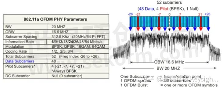
802.11a OFDM Physical Parameters
802.11a OFDM Frame Structure
The basic frame structure of an 802.11a burst contains a preamble field followed by a SIGNAL field and multiple data fields. At the start of the burst, a preamble is transmitted at a well-known magnitude and phase. The preamble is used for synchronization and channel equalization. The SIGNAL field (not used in HIPERLAN 2 signals) is transmitted using BPSK and contains the length, modulation type, and data rate information. Then multiple OFDM symbols containing the input data bits are appended to complete the burst.
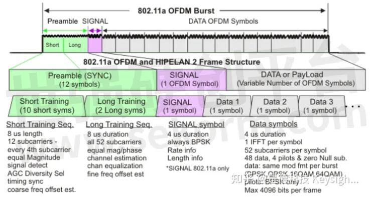
802.11a OFDM and HIPELAN/2 Frame Structure
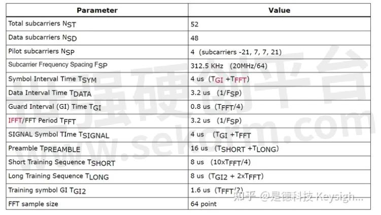
802.11a OFDM Signal Timing Parameters
The following table lists the timing parameters associated with the 802.11a signal:
802.11a Timing Related Parameters
MIMO Antennas
MIMO systems are those that use multiple transmit antennas and multiple receive antennas. The basic trick with MIMO is to include channel training signals that are unique to each transmitter so that each source can be readily identified. This can be as easy as picking different pilot sub-carriers. This structure can be different for uplink and downlink. There are different types of MIMO depending on how the data are mapped into the multiple transmit antennas. There can be redundant transmissions or independent bits carried on each antenna, which is more common. Remember the bits at this level are heavily encoded, typically with turbo-codes for forward error correction. Loss of individual bits will often be corrected in the decoding. Figure 7 shows the theoretical channel capacity with different types of MIMO and a system with single input and output antennae (SISO).
CAPACITY COMPARISON
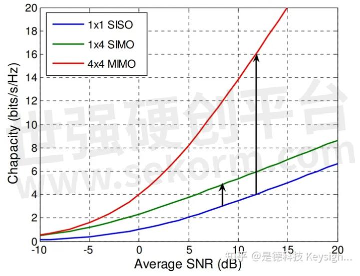
Figure 7. MIMO has major advantages over SISO
The transmission model for MIMO is shown in figure 8. This shows 4 x 4 MIMO as an example.
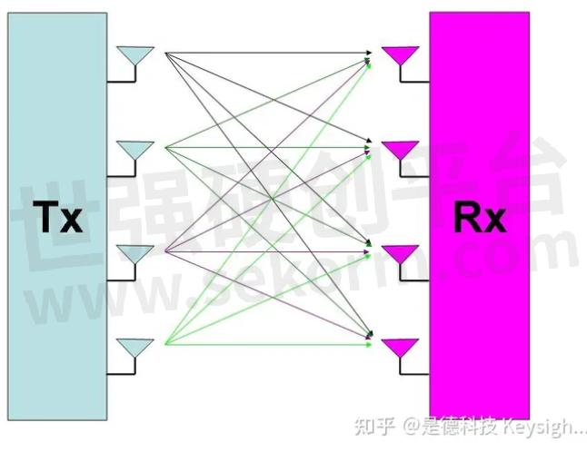
Figure 8. 4x4 MIMO system
As shown, there are 16 different transmission paths, one from each transmit antenna to each receive antenna.
Full MIMO requires two or more transmitters and two or more receivers. For a system to be described as MIMO, it must have at least as many receivers as there are transmit streams. The number of transmit streams should not be confused with the number of transmit antennas. (Consider TX diversity in which two transmitters are present but each sends the same data stream.) One other crucial factor for MIMO operation is that the transmissions from each antenna must be uniquely identifiable so that each receiver can determine what combination of transmissions has been received. This identification is usually done with pilot signals, which use orthogonal patterns for each antenna.
Conclusions:
− OFDM offers significant advantages as a next-generation air interface technology when compared to the CDMA technology upon which 3rd generation cellular systems are based:
− OFDM can easily be scaled up to wide channels that are more resistant to fading.
− OFDM channel equalizers are much simpler to implement than are CDMA equalizers as the OFDM signal is represented in the frequency domain rather than the time domain.
− Because of the long symbols used for OFDM, it can be made completely resistant to multipath.
− OFDM is better suited to MIMO. The frequency domain representation of the signal enables easy pre-coding to match the signal to the frequency and phase characteristics of the multipath radio channel.
There are significant design challenges in bringing OFDM technology to market. KEYSIGHT Technologies, along with its partners, is working to provide the tools engineers need, from design automation solutions and flexible RF and digital instrumentation for early R&D, to interoperability and conformance tests.
A review of OFDM system problems and solutions, analysis and troubleshooting, and a practical COTS approach that utilizes Keysight SystemVue.
Use Case: Making a Custom OFDM Measurement with a Spectrum Analyzer
This topic describes how to configure the spectrum analyzers to make a Custom OFDM measurement including instructions to create OFDM Phy Layer signal description setup files necessary to configure the demodulator to analyze custom, or non-standard, OFDM signals.
Overview
You
must manually configure the SA Custom OFDM demodulator to measure your
signal. The process to configure the SA Custom OFDM demodulator consists
of three steps:
1. Specify the high-level PHY Layer and FFT parameters for the OFDM signal under test;
2. Describe the detailed signal frame structure in the form of 4 configuration files that define each subcarrier in each symbol.
3. Configure the measurement setup parameters, e.g. synchronization type, result length, etc.
Signal Setup
Before
selecting the Custom OFDM demodulation mode, make sure that the input
signal is correctly captured by the analyzer. Specify the SA basic
signal measurement setup parameters so that the input signal is fully
captured including; the center frequency, span, input range, etc.. You
can use the Spectrum and Time traces to verify that the signal of interest is properly captured.
Tutorial Demo Signal
This measurement tutorial uses a demo signal based on an 802.11a/g OFDM signal. The Custom OFDM configuration developed below can be used with the supplied VSA Demo Signal "CustomOFDM_80211a" which uses the "CustomOFDM_80211a.sdf" recorded signal.
To use the demo signal, recall the "CustomOFDM_80211a" Demo Signal, click File > Recall > Recall Demo > navigate to the "%PROGRAMFILES%\Keysight\89600 Software <ReleaseVersion>\89600 VSA Software\Help\Signals\Custom OFDM" folder and click the "CustomOFDM_80211a" Demo Signal File.
Configuring the Demodulator
Step 1 - Specify the signal symbol FFT parameters
To begin, select the Custom OFDM demodulator, click MeasSetup > Measurement Type > General Purpose > Custom OFDM. Then open the Custom OFDM Demod Properties dialog, click MeasSetup > Custom OFDM Demod Properties.. .
Loading the "CustomOFDM_80211a.htm" Demo Signal File will auto-select the Custom OFDM demodulator.
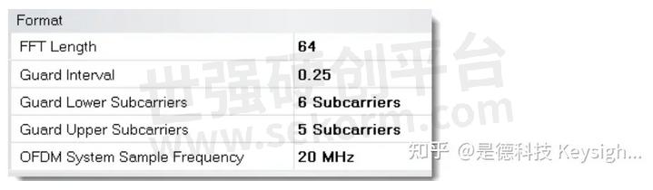
Select the Demod Properties Format tab and specify the following five FFT parameters: FFT Length, Guard Interval, Guard Lower Subcarriers, Guard Upper Subcarriers, and OFDM System Sample Frequency.
The PHY Layer parameters are typically located in the early part of the technical standard.
These particular OFDM setup parameter values are specific to the "CustomOFDM_80211a.sdf" signal under test.
Note:
●The FFT Length can be specified in any even incremental value between 4 and 65536.
●The Guard Interval is usually between 1/16 and 1/4 and is entered in decimal notation.
●The number of active subcarriers is generally fewer than 2N, with empty guard subcarriers allocated on either side of the signal.
●The number of active subcarriers is usually odd, due to the null subcarrier (subcarrier 0) in the center, and equal quantities on either side. This results in an odd number of guard subcarriers. Most standards define the lower guard region with one more subcarrier than the upper.
Step 2 - Define the Detailed OFDM Preamble and Payload Symbol Data
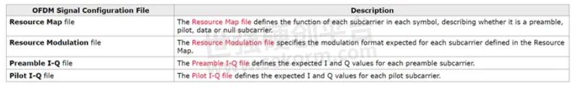
Because this is a non-standard custom OFDM signal, the OFDM signal frame structure, preamble, and data symbols must be described in detail so that the VSA can correctly demodulate the signal. The VSA uses the following 4 OFDM configuration text files to define the OFDM symbol data:
The OFDM Signal configuration files are all simple text files consisting of numeric values separated by spaces, commas, tabs, or CR/LF. The file extension may be .txt or .csv. For clarity, it may be useful to organize these files with one row of values per symbol, but this is entirely optional.
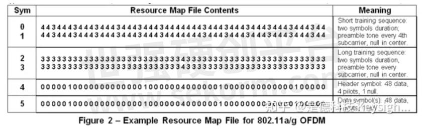
Resource Map File
The Resource Map file defines the function of each subcarrier in each symbol, describing whether the subcarrier is a preamble, pilot, data, or null subcarrier type. The Resource Map file must contain one value for each active (i.e. non-guard) subcarrier, including the "DC" center subcarrier. Thus, the map for an 802.11a/g signal (FFT size of 64 with 11 guard subcarriers) will contain 53 values per symbol.
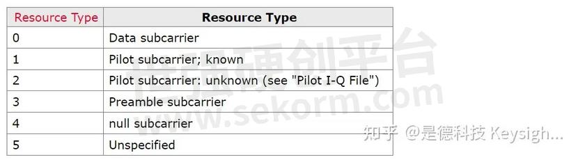
The Resource Type may have values as high as 1023 per symbol depending on the FFT size. For certain advanced configurations (described later in this note), the Resource Type is treated as a 10-bit number, with the higher-level bits used to indicate items such as user number,MIMOantenna number, etc.:
Note: If the number of pilots in the pilot values array is insufficient to populate the resource map, the pilots values are repeated to fill the remaining resource map pilot locations.
Resource Repeat Index:
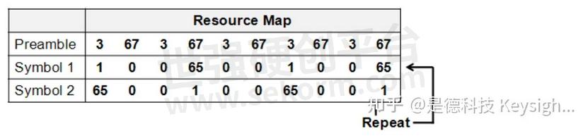
The resource map for most OFDM signals will consist of one or more preamble symbols, sometimes followed by specialized header symbols, followed by a repeating pattern of similarly-formatted symbols. For these repeating symbols, it is only necessary to define the pattern once; the Resource Repeat Index tells the analyzer how to loop when the end of the Resource Map file is reached.
In the preceding Example Resource Map File for 802.11a/g OFDM, the Resource Repeat Index is 5, meaning that the 5th symbol (starting count from zero) is to be repeated indefinitely. If the index was 4, the 4th and 5th symbols would be repeated in sequence, and so on.

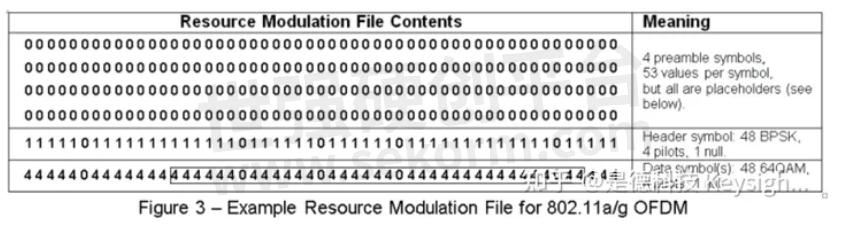
Resource Modulation File
The Resource Modulation file specifies the modulation format expected for each subcarrier defined in the Resource Map. The Resource Modulation file contains one Resource Modulation value for every subcarrier defined in the Resource Map file. The Resource Modulation value does not directly specify the modulation format. The Resource Modulation is an index that references a QAM Identifier value that is also in index that references a QAM Level value that specifies the subcarrier QAM Level (for example 4QAM, 8QAM, 16QAM... etc.).
The QAM Identifiers parameter:
The QAM Identifiers parameter is specified in the Format tab > QAM Idenifiers text box (Custom OFDM Demod Properties dialog box).

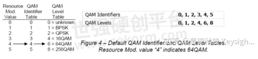
As previously mentioned, the Resource Modulation file does not define the modulation type directly. Rather, the Resource Modulation is an index into the QAM Identifier table, which provides an index into the QAM Level table. Both of these parameter tables are specified on the Format tab of Custom OFDM Demod Properties dialog box. In the example below (fig. 4), a Resource Modulation value of 4 points to the 4th value (counting from zero) in the QAM Identifier table, which is also 4. These values result in a specified modulation format of 64QAM as follows; A QAM Identifier equal to 4 points to the 4th value in the QAM Level table which is 6 that specifies a 64QAM modulation format.
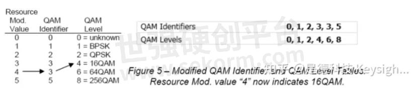
The advantage to this scheme is that subcarrier modulation definitions can be changed quickly and easily without modifying the Resource Modulation file. Figure 5 shows how all subcarriers defined as 64QAM can be changed to 16QAM by simply modifying a single value in the QAM Identifier table (change from a 4 to a 3). In this example, the Resource Mod value of 4 is not changed and continues to point to the 4th value in the QAM Identifier table. However, the resulting index into the QAM Level table has changed to 3 which points to the third value in the QAM level table which is 4 specifying 16QAM.
The Custom OFDM demodulator supports the following QAM Levels:

Auto-detecting the modulation format:
Resource Modulation value zero “unknown” is a special case that can greatly simplify Custom OFDM setup. Resource Modulation zero instructs the demodulator to detect the format automatically based on a statistical algorithm. This algorithm computes a single result (modulation format) for all subcarriers specified as zero. Resource Modulation "zero" is normally used for a group of subcarriers spread across one or more symbols that all utilize the same modulation format.
The auto-detection algorithm does not support any QAM modulation greater than 256QAM. If your signal uses these modulation formats, you must explicitly use QAM levels (9-16) shown in the table above. Auto-detection algorithm does support 8-QAM and rotated versions of BPSK and QPSK. There is no QAM level value corresponding to these formats, so if your signal uses one of these, auto-detection is the only way to demodulate these subcarriers correctly.
Placeholder values:
The Resource Modulation file must always have the same number of values as the Resource Map file. However, not all Resource Modulation values are actually used by the demodulator. This is because some subcarriers have no modulation (Resource Type 4 or 5) and some are defined in separate I-Q files (Resource Types 1 and 3, see next section). The Resource Modulation values provided for these subcarriers will thus be ignored and can be set to any number desired, even numbers assigned to other formats. In the example shown above, zero is used as a placeholder even though it usually means ‘unknown‘ modulation format.
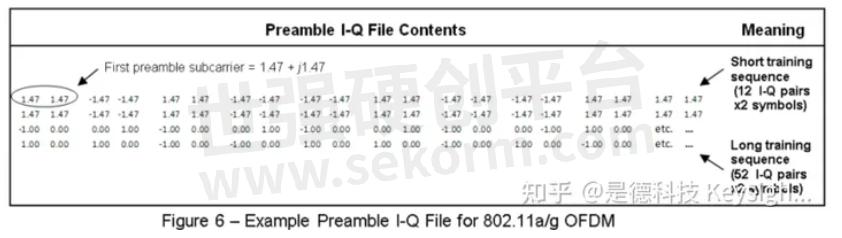
Preamble I-Q File
The Preamble I-Q file defines the expected I and Q values for each preamble subcarrier. This file contains I and Q values for every preamble subcarrier (Resource Type 3) defined in the Resource Map file. Each time the demodulator encounters a “3” in the Resource Map file, it reads the next two values from the Preamble I-Q file and uses these values as the ideal I-Q location for that preamble subcarrier.
The "I" value is listed first, then the Q value second – do not swap the values!
I-Q values are interpreted as being relative to the average constellation power (i.e. the “constellation reference power”), which is defined as 1.00. A preamble subcarrier boosted by 3 dB would thus have a magnitude of 1.414, e.g. 0+j1.414, 1.00+j1.00, etc.
In most OFDM signals the preamble subcarriers are a constant magnitude and may, or may not, be boosted relative to the constellation reference power. The phase of each preamble subcarrier is usually one of two values (for BPSK) or four values (for QPSK), and typically follows a PRBS sequence defined by the standard. All of this information must be known in order to construct the preamble I-Q file.
The quantity of values in the Preamble I-Q file is equal to twice the total number of preamble subcarriers, summed across all preamble symbols. The Preamble I-Q file contains values only for preamble subcarriers, not data, pilot or null subcarriers.
In the following example, the first I-Q pair is read as 1.47 + j1.47, and refers to the first preamble subcarrier designated by the Resource Map file in Figure 2, i.e. the third subcarrier in the first symbol. Based on these I-Q values, the analyzer expects this preamble subcarrier to have a magnitude of 2.03 and phase of 45 degrees, relative to the constellation reference power.
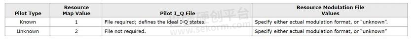
Pilot I-Q File
The Pilot I-Q file provide the ideal I-Q locations for each known pilot (resource type = 1) shown in the Resource Map file. The quantity of values in this file is thus equal to twice the number of pilots defined in the Resource Map.
Unknown pilots:
in many cases, it will be simpler to define the pilots as "Unknown" (Resource Type = 2), and define only the expected constellation shape (i.e. BPSK) and boosting level. Based on this information, the analyzer will determine the ideal states empirically, and not require a Pilot I-Q file. No knowledge of the Pilot PRBS sequence is therefore required.
Note that "Known" pilots (Resource Type = 1) allow the demodulator to synchronize more reliably under poor SNR conditions. In addition, the received pilot PRBS sequence is verified against the sequence defined in the Pilot I-Q file so it can detect coding errors in the signal under test.
"Known" pilots can also be used for synchronization, in the case of signals having no preamble. This is not possible with "Unknown"pilots.
In summary, the choice of "Known"versus "Unknown" pilots effects the values specified in the configuration files as follows:\
Note:
1) For
BPSK pilots that are rotated to lie entirely on the vertical (Q) axis,
always use unknown modulation format, and either: a) unknown pilots; or
b) known pilots plus a valid Pilot IQ file.
2) Unknown pilots are
assumed to have magnitudes of 1.00 relative to the constellation
reference power. If not, a relative boosting factor must be specified on
the Format tab.
Step 3 – Configure the Measurement Parameters
The setup options for the Flexible OFDM demodulator are similar to those provided for the existing 89600 VSA OFDM formats. More complete descriptions can be found in the Custom OFDM Demodulation Properties Dialog Box:
Format Tab
●Format Details: Boosting
●Signal is Bursted (when selected, also set Pulse Search parameters on the Time tab).
●Boosting: by default, the analyzer assumes that all modulation types are scaled the same way, i.e. the average power is 1.00. This section of the setup menu allows separate scaling factors for each modulation type, for each user number (see below) and for unknown pilots.
Time Tab:
●Measurement Interval and Offset
selects the number of symbols to be displayed.
●Result Length
selects the number of symbols to be demodulated.
●Result Length selection
set to “automatic”, the analyzer demodulates only to the end of the current burst.
●Search length
sets the amount of waveform to acquire per measurement. Typically set to two bursts “on” times plus one burst “off” time.
●Pulse search
selected, the analyzer automatically aligns the measurement with the rising edge of the RF envelope. If not selected, use triggering to position the first symbol near the start of the time record.
Equalizer & Tracking Tab:
●Equalizer use Data/Pilots/Preamble
use some or all of the subcarriers for Equalizer training. Note: to analyze an OFDM signal that has no preamble, de-select “Use Preamble” in this section, and configure the analyzer for “known” pilots.
●Equalizer averaging mode
determines whether channel response data, taken across multiple symbols, should be averaged using Equal Weight or Least Squares. Equal Weight averaging is generally more effective at noise reduction and is recommended unless otherwise required by the standard.
●Track Amplitude/Phase/Timing
same as current OFDM demodulators.
Advanced Tab:
●Extended Frequency Lock Range
allows the demodulator to remain locked with a larger center frequency offset, with some tradeoff of noise immunity.
●Synchronization Mode
use “Time Correlation” for traditional preamble or pilot-based sync; “Cyclic Prefix” may be of value for unknown, missing or poorly-formed prefixes.
Advanced Topics
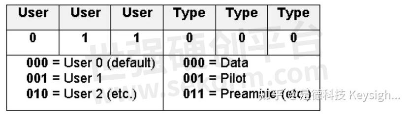
1. Multi-User OFDM
In some forms of OFDM, the physical resource (i.e. the set of subcarriers) is shared among multiple users. The subcarriers for one user may have a different modulation format and/or power level than those for other users making it desirable to view measurement results on a per-user basis.
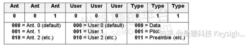
To accomplish this, each subcarrier in the Resource Map can be assigned to an arbitrary User Number between 0 and 7. The User Number and Resource Type are entered into the Resource Map as a single 6-bit number, equal to (User Number x8) + Resource Type.
When programmed for multiple users, the VSA “Data Burst Info” table displays individual results for each user number, as shown in Figure 7.
User numbers are valuable even for non-OFDMA signals. For example:
●When using “unknown” modulation format, autodetection is performed separately for each user number, so that several regions can be autodetected independently.
●Constellation reference power (i.e. boosting ratio) can be set separately for each user number, enabling measurements of signals with multiple power levels.
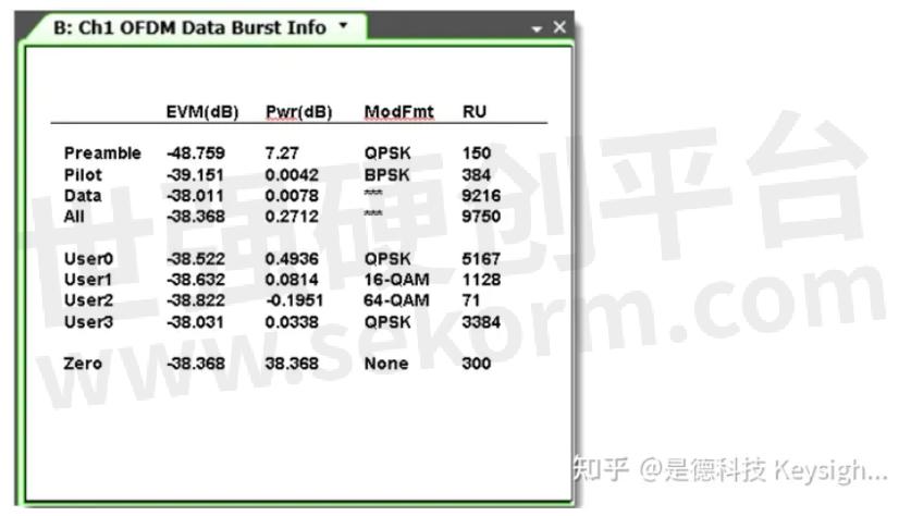
Figure 7 – OFDM Data Burst Info table, showing results tabulated by user number.
2. MIMO Analysis
The Custom OFDM demodulator can be configured to recover and analyze up to 4 MIMO transmit streams. This is accomplished using the same configuration files described earlier in this note but with certain modifications.
Configuration details depend on the type of MIMO being analyzed:
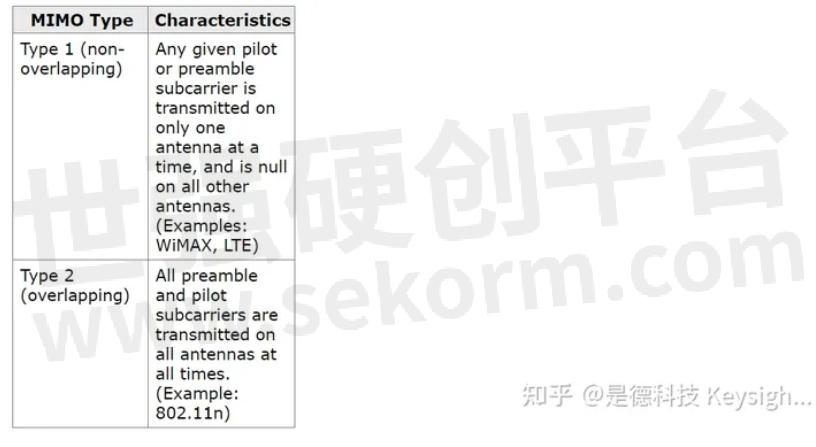
For both types of MIMO, it is assumed that data subcarriers are transmitted simultaneously on all antennas, and have the same modulation format on all antennas.
Configuring Type 1 MIMO: To further illustrate this class of signals, consider the simple MIMO signal shown below.
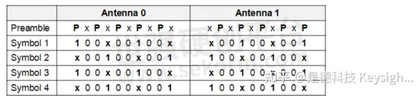
Figure 8 –Type 1 MIMO Signal (simplified example)
Note: The non-overlapping preamble tones (P) in the first symbol, and the non-overlapping pilot tones (1) in the subsequent symbols. The required configuration file modifications are as follows:
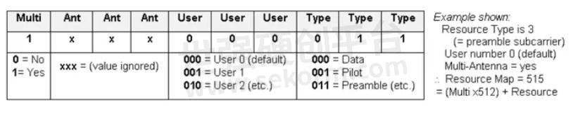
- Resource Map file: For each preamble or pilot subcarrier, treat the Resource Type value as a 9-bit number, with the upper three bits representing the antenna number. Thus, to assign an antenna number, add (Antenna Number x64) to the Resource Type. When an antenna number is assigned to a resource, that resource is assumed to be active on that antenna only, and null on all other antennas. Antenna number may change from symbol to symbol.
Example Details:
●Resource Type is 3 (= preamble subcarrier)
●User number is 0 (default)
●Antenna number is 1
●Resource Map value = 67 = (Ant No. x64) + Resource
For the simplified MIMO signal shown above, the modified Resource Map would appear as follows – notice how it describes the signals on both antennas at once.
- Resource Modulation file: this file requires no modification; as before, it contains one Resource Modulation value for each subcarrier shown in the Resource Map file.
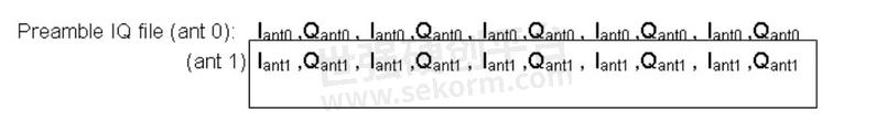
- Preamble and Pilot IQ files: because these files also describe multiple signals at once, they will generally have more entries than an SISO file. Beyond that, the basic rules still apply: include one I-Q pair, scaled to the constellation reference power, for each preamble or pilot shown on the Resource Map (omitting data, null and guard subcarriers), and enter them in the same sequence as they appear in the Resource Map file.
In the simple MIMO Resource Map above, the preamble tones alternate between antenna 0 and antenna 1. In the Preamble I-Q file, the values alternate the same way, i.e.:

The same is true for the Pilot IQ file, where additional lines are needed because the pilot sequence repeats across multiple symbols:

●Configuring Type 2 MIMO: this class of signals is represented by the following simplified example:
Notice how preamble (P) and pilot (1) subcarriers are overlapping, i.e. active on both antennas simultaneously. This is handled within the configuration files as shown below.
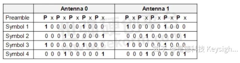
Figure 9 –Type 2 MIMO Signal (simplified example)
- Resource Map file: because the preamble and pilots are used simultaneously on both antennas, it is not necessary to assign an antenna number. Instead, one further bit is used in the Resource Map value to indicate that the given resource is present on all antennas. This is bit #10, which means that a multi-antenna resource will have a value of (512 + Resource Type).
For the simplified MIMO signal above, the Resource Map would be:

- Resource Modulation file: this file requires no modification; as before, it contains one Resource Modulation value for each subcarrier shown in the Resource Map file.
- Preamble and Pilot IQ files: although the preamble and pilot subcarriers are present on both antennas simultaneously, they will generally not have the same I-Q values, so they must be specified separately. In their respective IQ files, the complete set of IQ data for antenna 0 is provided first, followed by the IQ data for antenna 1, and so on.
The analyzer assumes that the number of antennas to be analyzed is equal to the number of hardware inputs currently selected on the analyzer’s Input Channels menu.
The Preamble IQ file for the simplified MIMO signal will thus include two lines, one for antenna 0 and one for antenna 1. Each line contains the I-Q pairs that describe the five preamble tones on that antenna:
Likewise, the Pilot IQ file for this signal will contain data for two symbols on antenna 0 (because of the two-symbol repeat sequence), followed by data for two symbols on antenna 1.

- |
- +1 赞 0
- 收藏
- 评论 0
本文由星晴123转载自Keysight zhihu,原文标题为:OFDM原理 (英文版),本站所有转载文章系出于传递更多信息之目的,且明确注明来源,不希望被转载的媒体或个人可与我们联系,我们将立即进行删除处理。
相关研发服务和供应服务
相关推荐

Massive MIMO是什么意思?
Massive MIMO是第五代移动通信(5G)中提高系统容量和频谱利用率的关键技术,是大量天线的波束赋形。
技术探讨 发布时间 : 2024-06-15

什么是波束成形?
波束成形就是对波束的形状进行构造,波束成形、波束形成、波束成型和波束赋形意思相同。本文KEYSIGHT分析了Wi-Fi为什么要用波束赋形,并详细介绍了波束赋形的方法和波束赋形系統。
技术探讨 发布时间 : 2024-03-25

解析频域和时域的关系
频域和时域分析是分析信号的基本方法,是从不同的角度来描述信号的特性。信号的特性可以在时域上和频率域上得到反映。本文是德科技解析了关于频域和时域的关系。
技术探讨 发布时间 : 2024-03-22

Keysight(是德科技)测试仪器分销产品选型指南(英文)
目录- BenchVue Control and Analysis Software RF Bench and Handheld Instruments Handheld Spectrum Analyzers FieldFox Handheld Analyzers Spectrum Analyzers, Signal Analyzer Audio Analyzer and Signal Generator Power Sensors and Power Meters RF and Microwave Test Accessories Vector Network Analyzers and ECal Modules Essential Bench Oscilloscopes, Applications, and Probes Digital Multimeters Function/Arbitrary Waveform Generators Data Acquisition/Switch Units USB Products and Connectivity Frequency Counters/Timers Power Supplies Bench Power Supplies System Power Supplies Precision Power Supplies System Power Supplies(continued) DC Power Analyzer, SMUs, and DC Electronic Loads AC Power Sources LCR Meters Handheld Instruments
型号- U8480,B2911A,U1272A,N8926A,34460A,N7040A,U8000,N9340B,53140,N5742A,N5766A,34905A,N9918A,N6735B,N8480,N5743A,N5767A,N1914A,3024T,3012T,U1273A,34904A,N6746B,N6734B,U3800,U1282A,N8948A,34470A,N7042A,N1913A,N5744A,N5768A,34903A,N8924A,N9916A,N9928A,34939A,N6701C,N8949A,U1271A,N8925A,N8937A,N7041A,N1912A,N9000B,N5745A,N5769A,N2819A,3022T,3034T,N6700C,34902A,N9917A,34938A,N6736B,U1600,8491A,DSOX1102G,DSOX1102A,N9320B,P-SERIES,33509B,N7020A,N1911A,N9344C,N5746A,N3302A,N2818A,34901A,34937A,U1701B,82357B,U1273AX,U2802A,N5181B,N2142A,U1281A,B2902A,4024A,N5747A,N3303A,8490G,N2805A,3032T,N6702C,U1700,N6705C,N8928A,N9342C,33519B,B2901A,N3304A,N5748A,34947A,N2804A,N8929A,N5171B,N9343C,N2140A,X-SERIES,B2912A,N3305A,U8903B,N5749A,4022A,34934A,4034A,34946A,8480D,3054T,U2702A,N3306A,U1733C,U1210,U2300,N5700,34945A,3458A,TU1453A,U2701A,B2962A,1146B,N3307A,1147B,N7026A,33600A,33612A,B2961A,N9322C,N9310A,U1731C,2002A,53200,2014A,3104T,U1610A,U2723A,33611A,2004A,U1732C,J7205A,34942A,U3606B,53210A,J7205B,U2722A,N1810UL,33622A,3102T,34941A,N8760A,2012A,2024A,U2500,U1620A,33512B,33500B,33621A,N1810TL,3004A,N6700,N6705,N8761A,N2821A,33511B,N3300,4104A,2022A,N2820A,U2600,33510B,33522B,3014T,N2843A,E36100B,33521B,N9962A,87106D,AC6804B,E4982A,DAQM905A,34950A-34959A,N6750,N9950A,N8740A,E36103B,U2020,EDUX1002A,N9951A,33520B,N7007A,83050A,N2962A,53131A,P9243A,E4981A,U2741A,34972A,E36102B,J7211B,J7211A,J7211C,E36320A,N8741A,AC6802B,DAQM903A,U1270,N9960A,E36311A,N8762A,E36105B,N6781A,U2000,E3641A,EDUX1002G,N2863B,AC6803B,DAQM904A,N8900,U1280,84904L,U2751A,34970A,N9961A,B2900,E36104B,E3640A,AC6800B,N2862B,6002A,E3600,E-SERIES,E36313A,DAQM900A,U1250,U5850,N8756A,N8732A,N8950A,AC6801B,10070D,DAQM902A,U2761A,34980A,E36300A,E36312A,N6782A,DAQM901A,E36106B,53220A,N8757A,87222D,N8733A,N8951A,87222E,N9952A,87104D,P9242A,E4980A,6004A,53132A,N6785A,N6773A,U1452A,B2980A,N6761A,N8754A,N8742A,P9241A,N2871A,53230A,N8700,N4985A-S50,U1240,N6784A,E4981A-001,E4981A-002,N8755A,U1453A,N8731A,N2870A,8495D,N2797A,87405B,N2894A,N5770A,8495B,87405C,34420A,E3647A,10833F,34921A-25A,10833G,10833A,10833B,4154A,10833C,10833D,N6775A,U1450A,N8736A,N6763A,U1232A,N8954A,N6751A,N8930A,N7550,N9923A,N2796A,N9935A,N2893A,N5771A,E36100,E3646A,6811C,N4985A-S30,4032A,N8737A,N6786A,N6774A,N8943A,N6762A,E5063A,10834A,N8955A,U1451A,8494G,N8931A,E3634A,U1233A,3052T,N2783B,P9371A,N2795A,N5772A,6813C,E3649A,6800C,6812C,N6753A,N8758A,U1460A,N6741B,U1242C,N8734A,U1242B,N8952A,N6777A,N8940A,N6765A,P9370A,N2891A,N2782B,EPM SERIES,53181A,N5761A,34931A-33A,34465A,E3648A,4054A,N8759A,N6764A,U1231A,U1461A,N6752A,E9320,83020A,N8735A,N8941A,N6776A,N2793A,DAQ970A,N2890A,L2060,N2781B,U1240C,N9914A,82350C,N5750A,N5762A,U2063,E5810B,N8934A,N6743B,N9926A,P1912A,N8946A,N6731B,N9938A,U1252B,E3643A,E3631A,N6755A,14585A,N2792A,N2780B,U1241C,N5763A,E4980AL,N5751A,E36300,E9300,N8923A,N9915A,N8935A,N6742B,N9927A,E3630A,U1241B,4052A,U1253B,E3642A,N6766A,34908A,N6754A,N2791A,N9912A,N8738A,N9936A,U1190,U2040,N5752A,N5764A,34450A,DAQM907A,N8932A,N8944A,34907A,N8920A,E3645A,N6745B,E3633A,N6733B,L2050,N2790A,U1251B,N8739A,N9913A,N9925A,N5741A,DAQM908A,N5765A,34461A,U2053,N8945A,N6732B,N9937A,N8957A,N8921A,E3632A,E3620A,N6756A,E3644A,N6744B

解析射频识别技术 (RFID)是什么及RFID和条形码的区别
RFID射频识别技术可以建置于所有的自动资料撷取领域, 其主要由射频 (RF)来提供非接触式的物体识别。目前RFID射频识别技术应用领域从工业自动化、门禁管理、动物识别和电子护照, 到医疗、票务与库存追踪不等。如今RFID解决方案在大型企业的研发计画上备受瞩目。举例来说, 自动识别领域的成长, RFID射频识别技术功不可没,它提供了非接触式智慧卡、生产自动化和电子供应链所需的基本技术。
设计经验 发布时间 : 2023-12-05

仿真分析工作者们是如何做到从繁琐的优化工作中解脱出来的?
PathWave System Design(SystemVue)是Keysight公司的前沿软件,用于通信系统中射频架构的高级设计和仿真。PathWave System Design (SystemVue)允许用户从系统的角度构建基带和RF架构。它包括两个仿真引擎,允许对任意体系结构进行仿真。数据流模拟引擎完全支持数字系统。
设计经验 发布时间 : 2023-11-03

为什么太赫兹技术是6G关键技术之一?
太赫兹技术在光学领域有一个为大众所熟知的名字 — 远红外线。下一代通信系统中的无线通信频段向毫米波、太赫兹和可见光等更高频段发展,与传统感知频段将产生越来越多的重叠。根据预测,6G通信技术将实现每秒 1 TB 的下载速度、1 微秒的时延以及无限的带宽。 6G通信将赋能我们通过各种创新方式与周围环境进行交互,包括即时通信、互联机器人、自治系统以及无线人工智能交互等。
设计经验 发布时间 : 2023-12-12

【经验】Keysight PathWave 89600 矢量信号分析软件进行矢量信号解调的原理和方法介绍
随着无线标准的发展,测量技术变得更加复杂,了解矢量信号解调的基本原理和方法变得越来越重要。凭借在数字信号处理、通信信号和矢量信号分析方面的扎实基础,Keysight PathWave 89600矢量信号分析软件在系统设计和研发方面发挥着巨大的作用。
设计经验 发布时间 : 2021-08-24

Keysight(是德科技)汽车测试产品选型指南(英文)
目录- Increasing Speed, Safety, and Reliability of In-Vehicle Communications Networks Data Acquisition for Accurate Automotive System Analysis Taming the Hostile RF World of Today’s Vehicles Managing Power in a Harsh Automotive Electrical Environment EMI Pre-Compliance Testing for Automotive Designs Handheld Instruments for Accurate Portable Automotive Testing General Bench Test and Accessories Test Automation with PathWave BenchVue Software
型号- N7026A,DAQ970A,4000 X,N2790A,N6705C,N5166B CXG,N6700 SERIES,3000T X-SERIES,N6700,3000T X,34980A,S-SERIES,6000 X,N9000B CXA,N7900,4000 X-SERIES,MSOX4154A,6000 X-SERIES,N7900 SERIES

PathWave Vector Signal Analysis (89600 VSA)
型号- 89604C,89601PSMC,89602C,89601BHQC,89601DVBC,89601CC1C,89600 VSA,89601AYAC,89601BHMC,89601B7RC,89601BHGC,89603C,89601CC2C,89601BHXC,89601CSDC,89601B7NC,89601BAXC,89601C,89601BHPC,89601BHTC,89601BHHC,89601BHNC,89601200C,89601101C,89601EVMC,89601301C,89601BHFC

PathWave Vector Signal Analysis (89600 VSA) Software CONFIGURATION GUIDE
型号- 89601BHXC,89601B7NC,89601BHPC,89601BHQC,89601BHTC,89601BHHC,89601BHNC,89601AYAC,89601BHMC,89601200C,89601B7RC,89600,89601301C,89601BHFC,89601BHGC

IxVerify 5G O-RAN O-RAN Radio Unit (O-RU) Chipset Design Testing and Validation Solution Using Pre-Silicon Emulation DATA SHEET
型号- N7631C,N7625ORNC,IXVERIFY 5G O-RAN,N7631ORNC,89601BHHC,89601BHNC,U5040IQEB,N7624ORNC,89601200C,89600,939-9592,U5040BSCB,939-9571,89601BHGC
RFID Modulation Analysis (IoT Modulation Analysis) 89600 VSA Software
型号- 89601BN,89600B,89601C,89601B,89601200C,89600,89601BHTC,89601BK-BHC

现货市场

服务
提供是德(Keysight),罗德(R&S)测试测量仪器租赁服务,包括网络分析仪、无线通讯综测仪、信号发生器、频谱分析仪、信号分析仪、电源等仪器租赁服务;租赁费用按月计算,租赁价格按仪器配置而定。
提交需求>
配备KEYSIGHT网络分析仪,可测量无线充电系统发射机/接收机线圈的阻抗,电感L、电阻R、电感C以及品质因数Q,仿真不同充电负载阻抗下的无线充电传输效率。支持到场/视频直播测试,资深专家全程指导。
实验室地址: 深圳 提交需求>
授权代理品牌:集成电路


授权代理品牌:分立元件


授权代理品牌:接插件及结构件


授权代理品牌:部件、组件及配件


授权代理品牌:电源及模块


授权代理品牌:电子材料


授权代理品牌:仪器仪表及测试配组件


授权代理品牌:电工工具及材料


授权代理品牌:机械电子元件


授权代理品牌:加工与定制


登录 | 立即注册
提交评论