MOS Tube H Bridge Motor Drive Circuit Diagram




H bridge is a typical DC motor control circuit, because its circuit shape resembles the letter H, so it is named "H bridge". Four audions constitute the four vertical legs of H, and the motor is the horizontal bar in H (note: the figure is only a schematic diagram, rather than a complete circuit diagram, in which the driving circuit of the audion is not drawn).
H bridge drive principle
1. Motor drive
Circuit first, single chip microcomputer can output dc signal, but its driving ability is limited, so MCU common drive signal, drive of power tube of the MOS tube, to produce a large current to drive motor, and size of duty ratio can pass drive chip control on the uniform voltage on the motor to reach the purpose of speed control. Motor drive mainly USES N channel MOSFET to build an H bridge drive circuit, H bridge is a typical DC motor control circuit, because its circuit shape resembles the letter H, so it is called an "H bridge". The four switches form the four vertical legs of H, and the motor is the horizontal bar in H. To make the motor run, a pair of switches on the diagonal must be switched on to control the positive and negative rotation of the motor through different current directions. Its connected circuit is shown in the figure.
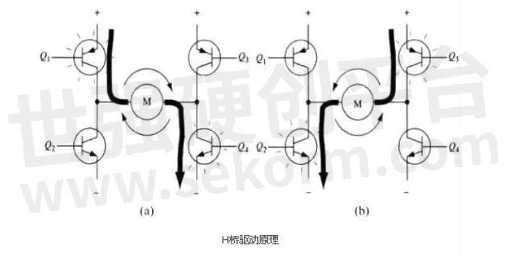
Fig.1
2. Driving principle of H bridge
In practice drive circuit usually uses a hardware circuit local control switch, motor drive board mainly USES two kinds of driver chips, one is full bridge drive HIP4082, one is half bridge drive IR2104, and the half bridge circuit is composed of two MOS transistor oscillation, the whole bridge circuit is composed of four MOS oscillator. Among them, the IR2104 half-bridge driver chip can drive high-end and low-end TWO N-channel MOSFET, can provide a larger grid drive current, and has hardware dead zone, hardware anti-on-arm conduction, and other functions. Two IR2104 type half-bridge driver chips can be used to form a complete DC motor H bridge drive circuit, and IR2104 low cost, function, output power relative to HIP4082 low, this plan adopts more.
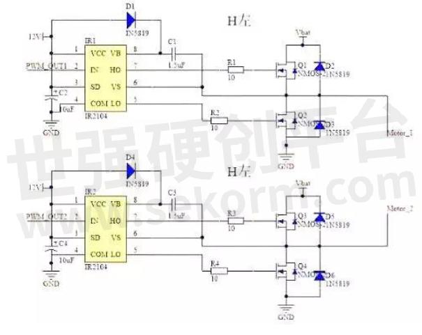
Fig.2
In addition, due to the driving circuit producing a larger injection current, to avoid impact on single chip microcomputer, it is better use isolated chips, there are many ways to isolate chip selection, such as 2801 and so on, these chips often do control bus driver, is driven to progress, after a certain condition, the output is the same as the input, can stop the data transmissions, the single chip microcomputer signal to drive chip, which in turn can't.
MOS tube H bridge motor drive circuit diagram
A typical DC motor control circuit is shown in Figure 3.
The circuit gets its name from the h-bridge drive circuit because it resembles the letter H. Four audions constitute the four vertical legs of H, and the motor is the horizontal bar in H (note: Figure 1 and the two subsequent figures are only diagrams, not the intact circuit diagram, in which the drive circuit of the audio has not been drawn).
As shown in the figure, the H-bridge motor drive circuit consists of 4 audions and a motor. To run the motor, a pair of transistors on the diagonal must be enabled. Depending on the conduction state of the triode pair, the current may flow through the motor from left to right or right to left, thus controlling the steering of the motor.

Fig.3
To run the motor, a pair of transistors on the diagonal must be switched on. For example, as shown in Figure 4, when the Q1 tube and Q4 tube are switched on, the current passes through the motor from the positive pole of the supply through Q1 from left to right, and then back to the negative pole of the supply through Q4. The current in this direction will drive the motor clockwise as shown by the current arrow in the figure. When triode Q1 and Q4 are on, the current will flow through the motor from left to right, thus driving the motor to rotate in a specific direction (the arrows around the motor indicate a clockwise direction).
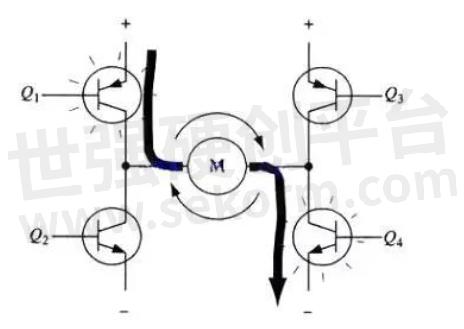
Fig.4
FIG. 3 shows the conduction of another pair of triodes Q2 and Q3, and the current will flow through the motor from right to left. When the transistor turns on Q2 and Q3, the current flows through the motor from right to left, driving the motor to rotate in the other direction (the arrows around the motor are counterclockwise).

Fig.5
Enable control and direction logic
When driving the motor, it is very important to ensure that the two transistors on the same side of bridge H do not conduct at the same time. If both Q1 and Q2 are switched on, the current will pass from the positive to the negative electrodes. At this point, there is no other load in the circuit except the transistor, so the current on the circuit may reach the maximum value (the current is only limited by the power supply performance), and even the transistor will be burnt out. Based on the above reasons, in the practice of driving circuits usually use hardware circuit local control transistor switch.
The modified circuit adds 4 gates and 2 non-gates to the base of the fundamental H-bridge circuit. The four are connected to the door with an "enable" signal so that the whole circuit can be switched on and off with this single signal. The two non-gates provide a direction input, which can ensure that at any time on the same side leg of the H bridge as long as a transistor can conduct. (Like the previous diagram in this section, FIG. 6 is not a perfect circuit diagram, especially when it is directly connected with the gate and triode, it cannot work normally).
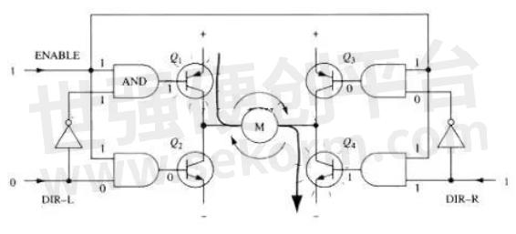
Fig.6
With the above method, the operation of the motor requires only three signals: two directional signals and an enabling signal. If dir-L signal is 0, the Dir-R signal is 1, and the enabling signal is 1, then triode Q1 and Q4 conduct on, and the current flows through the motor from left to right (as shown in FIG. 7); If the DIR-L signal becomes 1 and the Dir-R signal becomes 0, then Q2 and Q3 will be switched on, and the current will flow through the motor in reverse.
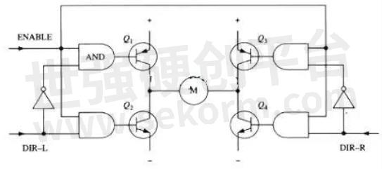
Fig.7
In practice, it is very difficult to make an H bridge with discrete components, but there are a lot of packaged H bridge integrated circuits in the market today, connected to the power supply, motor, and control signals that can be used, in the rated voltage and current is very easy to use. H bridge drive circuit with two discrete components:
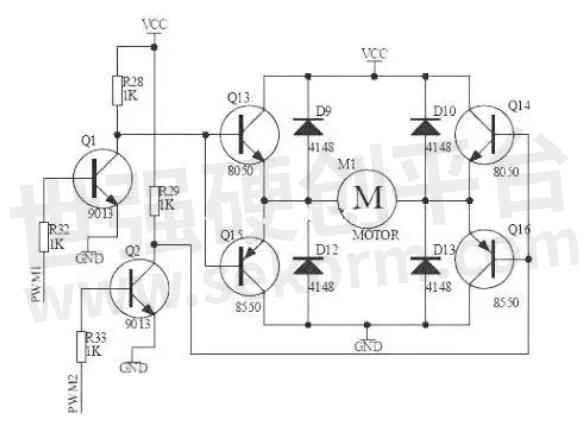
Fig.8
- |
- +1 赞 0
- 收藏
- 评论 0
本文由三年不鸣转载自HI-SEMICON News,原文标题为:MOS tube H bridge motor drive circuit diagram,本站所有转载文章系出于传递更多信息之目的,且明确注明来源,不希望被转载的媒体或个人可与我们联系,我们将立即进行删除处理。
相关推荐
MOS Switch Tube Selection and Principle Application
When the input voltage UI changes from high to low and the MOS tube changes from the on-off state to the cut-off state, the power UDD charges the stray capacitance CL via RD, charging time constant 1=RDCL, so the output voltage UO must pass a certain delay to change from the low level to the high level.
Switching Power Supply MOS Tube Loss
Switch Mode Power Supply, also known as switched Power Supply, switching converter, is a high-frequency Power conversion device, is a kind of Power Supply. Its function is to convert a potential voltage through different forms of architecture to the voltage or current required by the client. Switching power supplies convert voltages and currents between the inputs, which are mostly AC (such as mains power) or DC power, and the outputs, which are mostly devices requiring DC power, such as personal computers.
Experience sharing of classical MOS transistor level conversion circuit
Level switch in the circuit design is very common, because of circuit design, most of the time just like in the building blocks of the circuit module, and the circuit module, patchwork together is a electronic products. However, the voltage domain is often inconsistent between modules, so the level conversion circuit is used for the communication between modules.
Miller Effect on MOS Tube Switches
The gate drive process of MOSFET can be simply understood as the charging and discharging process of the input capacitance (mainly CGS of the gate source capacitance) of the MOSFET. When THE CGS reaches the threshold voltage, MOSFET will enter the opening state.
MOS Tube Knowledge, Must Read!
According to the size of PCB board, select the appropriate PMOS tube size, in the case of limited on-board area, choose the small package as far as possible; As far as possible to select common packaging, to prepare for the subsequent selection of appropriate replacement material.
MOS tube structure principle
Structure and symbol (take n-channel enhanced type as an example) -- Two high-concentration N-type areas are diffused on a low-concentration P-type silicon as drain and source, the semiconductor surface is covered with a silicon dioxide insulation layer and an electrode is drawn as a gate.
电子商城
现货市场
服务
可根据用户的MOSFET管进行参数检测出具报告,静态参数最大电压:7500V、检测最大电流6000A;动态参数最大电压:3300V、检测最大电流:4500A。该测试标准满足GB、IEC及行业标准等,具备可靠性评估及老化实验能力。
实验室地址: 西安 提交需求>
定制液冷板尺寸5mm*5mm~3m*1.8m,厚度2mm-100mm,单相液冷板散热能力最高300W/cm²。
最小起订量: 1片 提交需求>


登录 | 立即注册
提交评论