Overcome Challenges in Embedded Optical Interconnects Design




Introduction: Optical Technology in Embedded Design
The emergence of IoT in cloud computing and the demand for 4G and 5G networks worldwide are driving the increased use of Optical transceivers in a wide variety of applications: business, government, industrial, academic, and cloud servers in public and private networks. Both local area networks (LAN) and wide area networks (WAN) are demanding more bandwidth packed into smaller spaces, and traditional copper interconnects cannot satisfy the insatiable appetite of all the network servers and gateway devices. Furthermore, the next generation of networking devices will need to be even more compact and faster. According to market research firm Radiant Insight, the optical transceiver market will reach $9.9 billion by 2020, three times its 2013 level.
Optical transceivers are the key components that transform electrical signals to light over optical cables. At the receiving end, another optical transceiver will convert the light back to electrical signals as shown in Figure 1. Most transceivers operate with speeds of 10, 40, and 100 Gbps. When higher speed is needed, multiple lanes are used in parallel to deliver the required bandwidth.

Figure 1: Demonstration of conversion of digital data and fiber optic light signals.
What are the Advantages of Optical Networks?
Fiber optical networks or embedded communication systems have three key components: the optical transmitter, the fiber optical cable and the optical receiver. As described above, the transmitter converts electrical signals to light using either light-emitting diodes (LED) or laser diodes. At the receiving end, a photodetector is used to convert the light back to electrical signals. A transceiver combines the transmitter and receiver in one module.
The advantages of using fiber optics instead of copper include higher bandwidth, longer distance links, reduced weight, immunity to electromagnetic interference, and increased security.
Applications for Embedded Fiber Optics
Applications for embedded fiber optics are very broad and they often include projects that require very large bandwidth in confined areas, typically co-located with high-speed, high port count FPGAs or ASICs. Many of the civilian and military command and control monitoring systems (C4ISR), radar, FPGA interfaces, multiprocessor interconnects, CCD/CMOS imaging sensor arrays, high fidelity radar imagery, and systems requiring secure communications use fiber optics.
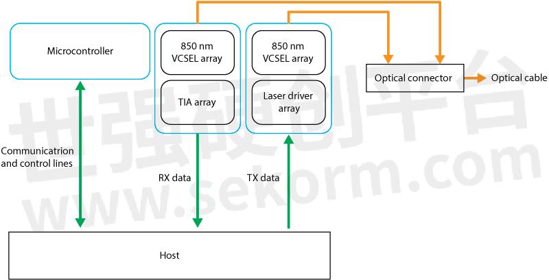
Figure 2: The block diagram of LightABLE™ LM SR4 module represents the typical functions of a transceiver
Challenges in Designing Embedded Systems with Optical Interconnects
There are three major challenges in designing embedded optical interconnects.
· Creating an embedded system to support maximum bandwidth with the smallest possible footprint.
· Designing or selecting the best optical interconnect able to perform in harsh environments with maximum MTBF.
· Future-proofing the embedded system to maximize the return on system investment.
Balancing performance, space, power, and cost is a constant tradeoff and challenge. The design will depend largely on the bandwidth requirements of the embedded system, which can be a single boardcomputer (SBC) or multiple boards that fit in a chassis. Some of these network systems need to support many Gbps, thus the system design will also depend on the size and throughput of the interconnect. Multiple components may be needed which can increase the size of the SBC or chassis, and power and cooling requirements can also impact the overall system footprint. Many commercial grade optical interconnects operate in a limited temperate range, and cannot handle the shock and vibration of harsh environments, and some systems may need to operate in humid conditions. All these environmental factors will directly or indirectly affect the operational performance and life span of the products. In other words, a high-performance system will typically consume more power and require better cooling resulting in larger size and costing more. Therefore, tradeoff in system design is always an important consideration.
In Search of the Best Fiber Optic Interconnect Solutions
There are many considerations in selecting the best fiber optics interconnect solution, and they often require tradeoffs. The main considerations include investment protection, product performance, form factors, reliability, and integration considerations. The following provides guidelines for selecting or designing optimal embedded fiber optic interconnect solutions.
Standard-based solutions protect purchase investments
System performance is impacted by many factors, and there are a few rules of thumb to bear in mind:
· The smallest form factor is desirable
· Always choose rugged and reliable solutions even if they cost more
· Guidelines for module integration and configuration should be observed
While there are many proprietary designs available, the best approach is to select VITA standard-based solutions because they are supported by a consortium along with a large ecosystem, so the design will be supported with upgrades over time. Additionally, the standard defines the technology and the connector specifications, which enables developers and integrators to select from multiple VITA-based vendors.
System performance is impacted by many factors
Fiber optics technology is capable of providing high-speed, low-latency, long-distance communication with no electrical noise interference. However, many factors will impact the true, sustained performance and potential distance of the communication links. These factors include communication error rate, link budget, and receiver sensitivity. Additionally, when doing system design, full-duplex must be part of the equation. Some new configurations can achieve up to 600 Gbps bandwidth, but there is overhead involved which may impact the actual throughput. For example, an unstable transceiver with a high error rate will cause the system to perform retransmission which will decrease the overall system performance. The measure of this phenomenon is referred to as bit error rate (BER).
For fiber interconnect devices or systems, the minimum BER should be 10-12. Higher performance can be achieved if BER is 10-15 or better. BER of 10-12 means that one error occurs every trillion transmissions. Additionally, a link budget greater than 13 dB with a receiver sensitivity of -12dBm is recommended
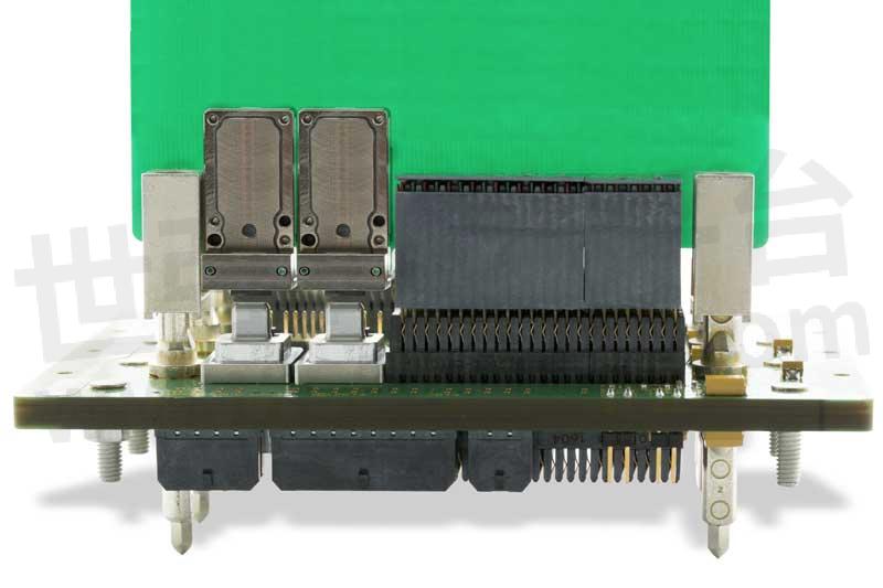
Figure 3: 600G LightCONEX plug-in module composed of two 24-lane transceiver side by side.
Smallest form factor is desirable
More and more embedded systems including single board computers (SBC) are using a smaller form factor. Therefore, it is important to select modules with the smallest footprint possible. Fiber optics transceiver modules can be as small as 1.3 cm × 1.3 cm (see Figure 4). Additionally, consider low profiles modules with a height of less than 5 mm. This will allow room for the SBC or systems to add additional functions on board.
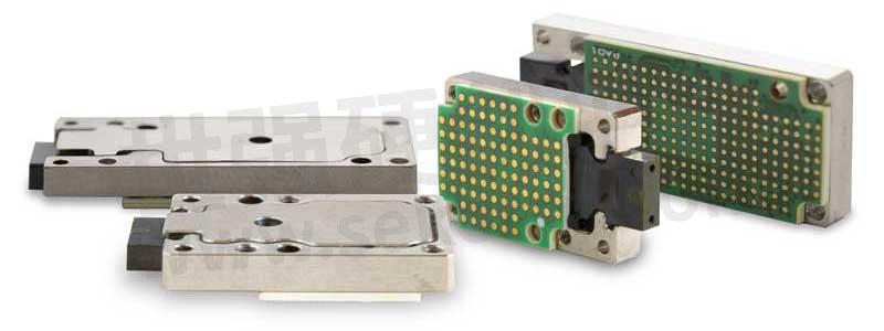
Figure 4: 150G and 300G LightCONEX Optical Transceivers
Always choose rugged and reliable solutions even when they cost more
Many fiber optics systems are used in harsh environments. As a result, commercial grade products will often fail or, at the minimum, have a shortened service life. It is important to choose solutions that will survive the environments of the target applications. Typical operating temperature should be from -40℃ to 100℃ or better with storage temperature from -57℃ to 125℃. In addition, if the module consumes less power (100 mW per lane or better), it will create less heat and help achieve better MTBF. Other considerations should include shock and vibration resistance, passing MIL-STD-883 or better. The module should also be sealed to prevent corrosion due to exposure to moisture. As a rule of thumb, it is recommended that products pass the following tests to ensure the highest quality.
MIL-STD-883:
· Vibration tests, Method 2007.3
· Mechanical shock tests, Method 2002.4
· Thermal shock tests, Method 1011.9
· Thermal cycling tests, Method 1010.8
MIL-STD-202:
· Damp heat tests, Method 103B MIL-STD-810:
· Cold storage tests, Method 502.5
Rules for module integration and configuration should be observed
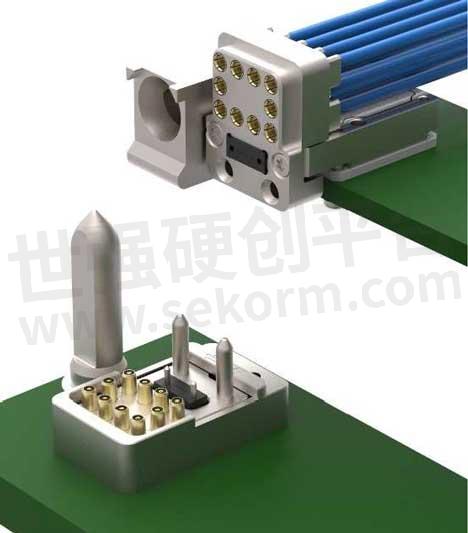
Figure 5: Illustration of a VPX blind mate connector comprising a 24 fiber MT ferrule and 10 RF coaxial connectors. The size of this connector meets VITA 66.4 standard.
A well-designed transceiver should take into account the connector choice and location, as well as ease of system integration and configuration. As shown in Figure 5, an active blind mate optical design will make connector mating much easier and reduce the chances of making connection mistakes.
Additionally, there are two other rules to follow when considering connector selection or design. First, follow the VITA 66.5 “Optical Interconnect on VPX, Spring Loaded Contact on Backplane” standard which defines the connector dimensions. Then place the board-edge, plug-in module connector, similar to ftlx8571d3bcvit1, near the edge of the board, integrating an active parallel optic transceiver, and a spring-loaded backplane connector developed for VPX systems (part of the VITA standard) as shown in Figure 6. This approach will limit any additional cabling needed to bring the signals to the edge of the SBC board.
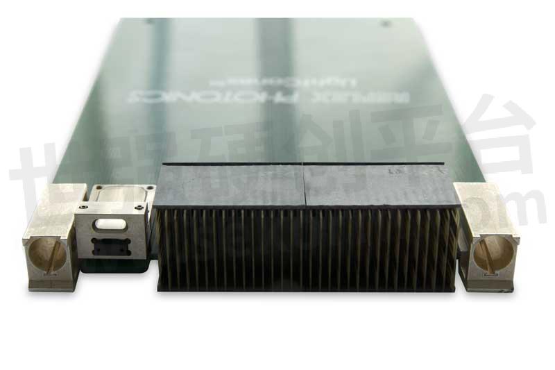
Figure 6: LightCONEX Active Blind Mate VPX Optical Interconnect
The Embedded Interconnects Design Checklist
The following paragraph can serve as a checklist for ease of use.
· Select solutions based on the VITA standard including VITA Section 6. This applies to the overall systems as well as the connectors.
· For optimal system performance, select modules with a low bit error rate (BER) such as 10-15.
· Select small form factor modules in the range of 1.5 cm x 1.5 cm, with height profiles less than 5 mm. This will provide extra space for the circuit board.
· Select rugged and reliable solutions that pass a minimum set of tests including the following:
MIL-STD-883:
· Vibration tests, Method 2007.3
· Mechanical shock tests, Method 2002.4
· Thermal shock tests, Method 1011.9
· Thermal cycling tests, Method 1010.8
MIL-STD-202:
· Damp heat tests, Method 103B
MIL-STD-810:
· Cold storage tests, Method 502.5
Select designs/modules that are easy to integrate. These include blind-mate and broad-edge connectors.
Conclusions
The above article has outlined the advantages and challenges of using fiber optical interconnects. To use fiber optic cables, the electrical signals need to be converted to light signals using fiber optic transceivers. While there are many challenges to embedded fiber optics design, the benefits are substantial. The guidelines and design checklist provided will help developers select the best solutions for their needs.
- |
- +1 赞 0
- 收藏
- 评论 0
本文由出山转载自Smiths Interconnect library,原文标题为:Overcome Challenges in Embedded Optical Interconnects Design,本站所有转载文章系出于传递更多信息之目的,且明确注明来源,不希望被转载的媒体或个人可与我们联系,我们将立即进行删除处理。
相关推荐
Smiths Interconnect’s Solutions Help the Optical Interconnect Design Challenges in Space
Aeronautical applications face many design challenges that are unique to their intended environment. The best practices for optical interconnect design for space applications include the use of radiation-resistant technology to defend against space radiation, the use of components and devices that are designed to operate in harsh environments, and meeting small SWaP and long-term reliability requirements. Finally, it is recommended to follow open standards like VPX and to look for solutions that comply with MIL and quality standards.
optical transceivers‘ SpaceABLE 10G 4TRX optical transceivers are fully operational on SES-17 satellite
Smiths Interconnect proudly announces another significant milestone in its spaceflight heritage. The company’s SpaceABLE® 10G 4TRX optical transceivers with patent-pending radiation-resistant design are now in service on Thales Alenia Space’s newest geostationary Ka-band satellite, SES-17.
Parallel Optics for Embedded System
Command, control, compute, communicate, intelligence, surveillance, and reconnaissance systems (C4ISR) rely on accurate views of local situations for decisions that are critical to national defense. Fiber optics interconnect has emerged as the only viable technology to carry the massive amount of information generated by high resolution radars, infra-red cameras and other sensors. Fiber optic-interconnect are small, immune to EMI and has superior bandwidth to traditional copper interconnect.
Sekorm is an Authorized Distributor of MERRY that is a Famous Acoustic Sensors Manufacturer
Sekorm said: “The new generation of electroacoustic products will play a more critical role, bringing more imagination and applications to human life. This cooperation with Merry will jointly promote business development and product extension.”
轻型10G LM系列、10G LL系列和28G LL系列加固型光收发器
型号- LLT12P9185330AA,LMR12P4182303AA,10G LM SERIES,LMX04P4182323AA,10G LL SERIES,LMX04P4182321AA,LMT12P4182330AA,LMR12P4184303AA,LMR12P4184301AA,LMR12P4183303AA,LLR12P9185301AA,LLR12P9185303AA,LMX04P4183321AA,LMX04P4183323AA,LLT12P928533003,LMR12P4183301AA,LLT12P618533001,LLR12P628530502,LLX04P9185323AA,LLR12P618530101,LLX04P9185321AA,LLX04P628532502,LLX04P428532101,LLT12P628532003,28G LL,10G LL,LLX12P418532101,10G LM,LMR12P4182301AA,LMT12P4183330AA,LLX04P618532101,28G LL SERIES,LLR12P928530102
商业航空航天连接解决方案
描述- Smiths Interconnect 是商业航空航天领域高可靠性连接产品和服务的主要供应商。公司提供高性能连接器解决方案、天线系统、射频组件和电缆组装,服务于飞行控制与导航系统、发动机系统、电源分配、卫星通信连接等多种航空应用。其技术品牌包括 EMC、Hypertac、IDI 等,专注于为高科技、高质量解决方案提供卓越性能,以满足高度安全和耐用性需求。此外,Smiths Interconnect 还提供广泛的认证标准和技术支持服务,以适应全球市场。
Reflex Photonics 光收发器选型指南
目录- New product highlights Rugged Transceivers for Defense Radiation-Resistant Optical Transceivers for Space VPX Applications for Defense and Space Rugged Transceivers for Commercial Aerospace and Industrial Optical Test Systems Product Ordering Information
型号- LIGHTABLE LL,LIGHTABLE LM,LMF10P418333101,SNT12C0100133,450-00042,LMX04P4182323AA,LCR12F418530301,LCR12C418530101,LCX04A418532101,LCR12C428530101,LLX04P918532101,LMR12P4184303AA,LMT12P4182330AA,SMR12P518430101,SPACEABLE SL,SPACEABLE SM,LIGHTABLE LH,LIGHTABLE LH-LM,SMR12P518230101,SNR12C0180133,LCR12B428530101,VMT12P618533001,LMX04P4183323AA,VMR12P618510101,SPACECONEX,SLR12P918530101,LIGHTCONEX28 LC,VMR12P618530101,SMX04P518232101,LCX04F418532101,450-00068,450-00069,450-00064,LMF12P418333301,450-00065,LMR12P4182303AA,450-00066,450-00067,SPACEABLE28,VMT12P618513001,LCK04P418500001,SMX04P518432101,LCT12C428533001,SLX04P918532101,SNT12C0050123,SPACEABLE SM BOARD V1,LMR12P4183303AA,450-00062,450-00063,LCR12A418530101,SNR12C0100123,LCX04B418532301,SMT12P518333001,LCR12B418530301,450-00054,SPACEABLE28 SL,SNAP12,LIGHTCONEX LC,LCX04C418532101,LHF120018330001,LLR12P918530101,SNT12C0180133,LCX12F418532101,SNT12C0050133,LLX12P418532301,LMT12P4183330AA,SNR12C0050123,SPACEABLE SL BOARD V2,SNT12C0180123,SMF10P518333101,LCR12C418530301,LCX04A418532301,LMX04P4182321AA,LCR12F418530101,LLX04P918532301,LIGHTCONEX28,LCT12B418533001,LCT12B428533001,LMR12P4184301AA,LHF120018310001,SMT12P518233001,LIGHTCONEX,VMX04P618532102,LIGHTABLE28,LMF10P418333301,SPACECONEX28 SC,LIGHTVISION VM,LMX04P4183321AA,VMX04P618512101,LCX12A-418532101,SNR12C0050133,LCX12C418532101,SLT12P918533001,LCX04C428532101,SPACECONEX28,LMR12P4182301AA,SMT12P518433001,SNR12C0100133,450-00070,SNR12C0180123,SMF12P518333101,LCK12P418500001,LHF100018330001,LMF12P418333101,SMX04P518332101,LCT12F418533001,LCX12B418532101,LCR12A418530301,LCT12C418533001,LIGHTABLE28 LL,LCX04B428532101,LCX04B418532101,LCR12B418530101,LLT12P918533001,LCT12A418533001,LMR12P4183301AA,SPACECONEX SC,SNT12C0100123,LCX04C418532301,LHF100018310001,LLX04P428532101,SLX12P518532101,SLX04P528532101,SMR12P518330101,LLX12P418532101,LLR12P918530301
LightConEx:用于VPX系统的光学插件和背板模块连接器
描述- 本资料介绍了Smiths Interconnect公司生产的LightCONEX系列光插拔模块连接器和背板模块连接器,适用于VPX系统。这些产品旨在满足国防工业对高密度、高速数据传输的需求,具有体积小、重量轻、带宽高等特点。
型号- LCT12D428532002,450-00104,450-00065,500-00262,450-00066,LCR12C428530502,LCX12P418532101,500-00267,VITA 67.3C,LCX04D418532101,500-00266,LCX04D428532502,VITA 67.3E,VITA 67.3D,415-00019,LCX12D418532101,415-00018,LCX04D418532302,500-00269,500-00268,415-00025,12TRX,415-00041,LCR12D428530502,VPX,500-00256,VPX SERIES,LCX04P4185321AA,LCX12C418532101,LCX04A4185321AA,LCX04P4185323AA,500-00258,415-00005,12RX,12TX,LCX04C418532101,415-00011,LCX04C418532301,415-00032,LCX04C428532502,LCT12C428532002,VITA 67.3F,415-00051,4TRX,450-00070
空间连接解决方案
描述- Smiths Interconnect作为太空应用中选择的首选供应商,提供安全、高效且高度可靠的连接解决方案。公司凭借超过80年的太空市场经验,设计并制造了小型化、轻量化且坚固耐用的产品,以应对振动、冲击、极端温度和辐射等恶劣环境。其技术品牌包括EMC、Hypertac、IDI、Lorch、Millitech、Plastronics、Reflex Photonics、RF Labs、Sabritec、TECOM、TRAK和HSI,这些品牌以其在高科技和高品质解决方案中的卓越性能而闻名。产品组合涵盖了高可靠性电气连接器和电缆组件、耐用嵌入式收发器、天线系统解决方案以及广泛的创新射频和微波解决方案。此外,Smiths Interconnect还为国际航天机构提供服务,并在多个空间飞行项目中表现出色。
型号- HC SERIES,K2TVA,AURORA,MWC,KU SERIES,AURORA SERIES,MWC SERIES,QT SERIES
国防连接解决方案
描述- Smiths Interconnect 提供一系列高可靠性连接解决方案,服务于军事和国防、医疗、半导体测试和工业市场。其产品包括集成微波组件、方向寻找器、卫星通信、数据链路、天线、光收发器和连接器解决方案等。公司技术品牌(如EMC、Hypertac、IDI、Lorch等)以其高性能和高品质解决方案而闻名,适用于安全关键应用和环境苛刻条件。产品线涵盖了高可靠性电气连接器、坚固嵌入式收发器、天线系统解决方案以及广泛的创新射频和微波解决方案。此外,Smiths Interconnect 还提供定制设计和全球支持服务。
Reliability Testing of COTS Fibre Optic Transceivers
With a dedicated design associated with critical circuit adjustments, COTS optical fiber transceivers can meet space applications requirements and are thus ready for short term deployment in large bandwidth communication satellites.
Unveiling the Advantages of Fiber Optic Transceiver Modules
Fiber optic transceiver modules have become indispensable components for ensuring reliable and high-speed data transmission. This article will delve into the various advantages of fiber optic transceiver modules and why they are essential for businesses and organizations.
Spacable 10G SL系列抗辐射光收发器
描述- 该资料介绍了SpaceABLE 10G SL系列抗辐射光收发器。这些产品专为太空应用设计,具有小型化、耐辐射、长寿命和高I/O密度等特点。它们适用于高吞吐量通信卫星、低地球轨道星座、地球同步轨道卫星以及板间和有效载荷间的连接。
型号- SLR12P918530101,SLX04P918532101,SL SERIES,SL,SLT12P918533001
电子商城
现货市场
服务
可烧录MCU/MPU,EPROM,EEPROM,FLASH,Nand Flash, PLD/CPLD,SD Card,TF Card, CF Card,eMMC Card,eMMC,MoviNand, OneNand等各类型IC,IC封装:DIP/SDIP/SOP/MSOP/QSOP/SSOP/TSOP/TSSOP/PLCC/QFP/QFN/MLP/MLF/BGA/CSP/SOT/DFN.
最小起订量: 1 提交需求>


登录 | 立即注册
提交评论