Driver technology of the new energy vehicle motor controller IGBT module


This paper introduces the design idea of IGBT module drive circuit of motor controller in large electric vehicle, expounds the characteristics of IGBT module, the design and protection of gate drive circuit, and the current, voltage and temperature protection of IGBT module in normal operation, and provides the corresponding design principle and verification scheme.
1. introduction
IGBT(Insulated Gate Bipolar Transistor),Insulated gate bipolar transistor is a composite fully controlled voltage-driven power semiconductor device composed of BJT (Bipolar Transistor) and MOS (Insulated Gate Field Effect Transistor), which has the advantages of high input impedance of MOSFET and low on-voltage drop of GTR.
IGBTCombining the advantages of the above two devices, the driving power is low and the saturation voltage is reduced.
It has become the mainstream of the development of power semiconductor devices, and is widely used in wind power, photovoltaic, electric vehicles, smart grid and other industries.
In the electric vehicle industry, IGBT is widely used in motor controllers, auxiliary power systems, and electric air conditioners. High-power IGBT is mostly used in motor controllers. Because the working environment of motor controllers in electric vehicles is relatively disturbed, parasitic parameters such as gate distributed capacitance of IGBT and Miller effect in actual switches directly affect the reliability of driving circuits [1].
When the motor is in use, the IGBT should be properly protected under the conditions of overcurrent, short circuit and overvoltage.
Over-current will cause the temperature of motor controller to rise, which can be detected by temperature sensor and protected by corresponding circuit. Generally, the overvoltage occurs when the IGBT is turned off, and the larger di/dt will produce a higher voltage on the parasitic inductance, which can be clamped by using a buffer circuit or appropriately reducing the switching rate.
After the short circuit happens, a huge current will be generated instantly, which will soon damage the IGBT. The overcurrent protection of the main control board is too late, and the hardware circuit must control the driving circuit to protect it instantly.
Therefore, in the process of driver design, whether the protection function is perfect or not is particularly important for the safe operation of the system.
1. IGBTCharacteristics of modules
1.1 Switching characteristics
The switching characteristics of IGBT are shown in Figure 1. When the IGBT module is turned off, VCE will generate peak high voltage due to leakage inductance [2], which changes with the change of dv/dt. As the switching time changes with the collector current, junction temperature and gate resistance (Rg), if the switching time becomes longer and the gate resistance becomes larger, the phenomenon of bridge arm through may occur due to insufficient dead time, which may damage the IGBT
At the same time, the switching loss occurs when the switch is turned on or off, and this characteristic changes with the junction temperature and driving resistance. Especially, the selection of Rg is very important. If Rg is too large, it will slow down the switching speed of IGBT, which can obviously reduce the switching overvoltage spike, but the switching loss will be correspondingly increased, which will increase the heat generation of IGBT. On the contrary, when Rg is too small, there may be too high peak voltage (=Ls X dIc/dt).
1.2 Capacitance characteristic
As shown in Figure 2 below, CGC, CGE and CCE are the parasitic capacitances between IGBT electrodes, Cies is the input capacitance, Coes is the output capacitance, and Cres is the reverse conductance capacitance [4].
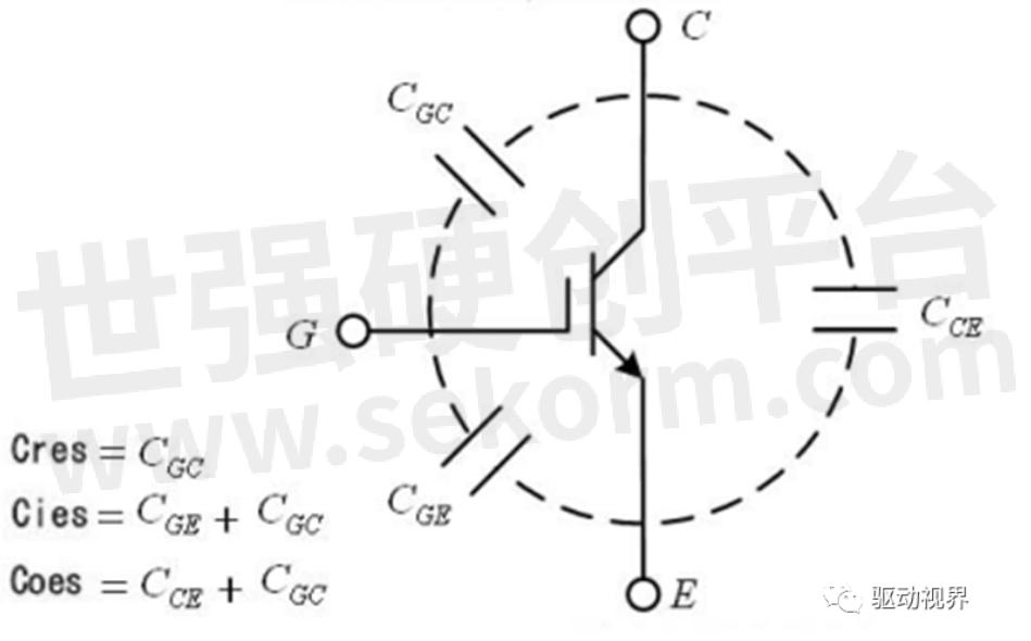
Fig. 2 parasitic capacitance between IGBT electrodes
As can be seen from Figure 2, the equivalent output capacitor Coes can provide another path for the C-pole of IGBT, so it will affect the change of the collector voltage of IGBT. When the IGBT is turned off, the load current will charge Coes. At this time, the change rate of the collector voltage of IGBT depends on the charging speed of the load current. Because the capacity of Coes is very small, its influence can be ignored in the case of high current. When the load current is small, the collector voltage of IGBT will change significantly.
The process of turning on and off IGBT can be equivalent to the process of charging and discharging parasitic capacitance (collector equivalent output capacitance).
The collector current and switching speed have influence on the change rate of collector voltage. When the IGBT current is small, the dv/dt of collector voltage is small; on the contrary, when the current increases, the dv/dt of collector voltage is large.
In the upper and lower legs of IGBT, when one leg is turned on and the other leg is turned off, a dVce/dt voltage change will be generated on the IGBT and the freewheeling diode of the turned-off leg, and a charging current iCG will be generated between the collector and the gate of the IGBT of the leg, which will be charged by parasitic capacitors CGC and CGE. At this time, if VGE is higher than the IGBT turn-on voltage, the leg may be through, resulting in IGBT damage.
1.3 area of safe operation
Safe working area (SOA) reflects the ability of a transistor to withstand a certain voltage and current at the same time.
The forward bias safe working area (FBSOA) when IGBT is turned on is surrounded by three boundary limits: current, voltage and power consumption.
The maximum collector current Icm is set to avoid dynamic locking, the maximum collector-emitter voltage Ucem is determined by the breakdown voltage of transistors in IGBT, and the maximum power consumption is determined by the maximum allowable junction temperature.
The longer the conduction time, the more serious the fever, and the narrower the safe working area.
The reverse bias safe operating area (RBSOA) of IGBT varies with the dVCE/dt when the IGBT is turned off. The higher the dVCE/dt, the narrower the RBSOA.The reverse bias safe operating area (RBSOA) of IGBT varies with the dVCE/dt when the IGBT is turned off. The higher the dVCE/dt, the narrower the RBSOA.
2. Driving of IGBT module for vehicle
2.1 Influence of grid resistance
The IGBT module is an insulated gate device. The gate-emitter (or gate-source) of the IGBT has a capacitive structure, and the parasitic inductance of the gate circuit is inevitable. If there is no gate resistor, the gate circuit will oscillate strongly under the excitation of the driver's driving pulse, so a resistor needs to be connected in series to quickly attenuate.
The turn-on and turn-off process of IGBT is mainly the process of charging and discharging parasitic capacitance or inductance, which are all reactive components. If there is no gate resistance, most of the driving power will be consumed on the output tube inside the driver, and its temperature will rise a lot. At the same time, the gate resistor can also adjust the on-off speed of the power switching device, but too fast driving speed will greatly increase the voltage and current change rate of the switching device, and the surge voltage and current borne by IGBT will increase. In the actual vehicle environment, it is best to use the non-inductive resistor. If it is a common resistor, it can be replaced by several resistors in parallel. On the one hand, it can reduce the loop inductance and its influence on the driving voltage waveform; on the other hand, multiple resistors can share the driving current, which is conducive to enhancing the thermal diffusion. If a single resistor is damaged, the system will be damaged.
When the IGBT is driven, the interference signal will cause the gate signal to be destroyed, resulting in a large reverse recovery surge voltage. When a very short blocking pulse is generated relative to the VGE of the IGBT, the freewheeling diode at the branch side of the IGBT turns on, and it enters the reverse recovery state in a very short time. During the reverse recovery process, it will enter the reverse recovery state only after fully accumulating carriers. At this time, if there is a narrow interference pulse, The fast freewheeling diode enters the reverse recovery state before fully accumulating carriers, and the depletion layer expands rapidly, which makes it produce strong DI/DT and DV/DT. During the reverse recovery of narrow pulse, a high reverse recovery surge voltage will be generated between GE of IGBT. At this time, the surge voltage can be reduced by increasing the gate input resistance RG, reducing the input circuit inductance, strengthening the buffer circuit, and adding a clamp circuit.
2.2 Gate drive circuit
As the switching characteristics and safe working area of IGBT change with the change of gate driving circuit, the performance of driving circuit will directly affect the normal operation of IGBT.
The driving circuit should provide proper forward gate voltage to IGBT.
After the IGBT is turned on.
The driving voltage and current provided by the driving circuit to the IGBT should have sufficient amplitude to keep the power output stage of the IGBT in saturation.
When the module is overloaded instantaneously, the driving power provided by the gate driving circuit should be sufficient to ensure that the IGBT does not exit the saturation region.
The voltage drop of IGBT after conduction is related to the applied VGE voltage. When the ICE current is constant, the higher the VGE, the lower the VCE value and the smaller the conduction loss of the device, which is beneficial to give full play to the working ability of the transistor.
However, VGE is not as high as possible. Generally, it is not allowed to exceed 20 V, because once overcurrent or short circuit occurs, the higher the gate voltage, the higher the current amplitude and the greater the possibility of IGBT damage.
Usually, +15V is appropriate for comprehensive consideration.
The gate limit voltage of IGBT is generally +20 V, and if the driving signal exceeds this range, the gate may be damaged.
Therefore, there should be a voltage limiting circuit between the driving circuit and the gate to protect the gate from breakdown when the gate voltage is too high.
Electric vehicle motor controller is driven by three-phase full bridge, and six groups of IGBT are needed to drive the three-phase bridge arm to work in PWM state. Each IGBT module needs a power supply isolated from other modules.
In order to improve the integration and reduce the cost, PWM control chips such as SG3525 are often used to output dual-channel PWM signals, drive pulse transformers and generate dual-channel power supplies. As shown in Figure 3, U3 in the figure is SG3525, a monolithic integrated PWM control chip with excellent performance, complete functions and strong versatility, which outputs two PWM signals with complementary duty ratios. It is simple, reliable, convenient and flexible to use, and the output drive is push-pull output, which increases the driving capacity. It contains internal undervoltage locking circuit, soft start control circuit and PWM latch. It has overcurrent protection function, adjustable frequency, and can limit the maximum duty cycle. In order to realize voltage isolation, PWM control works in an open loop state. Adjust the turns ratio of pulse transformer TR20, so that the output voltage of its upper winding is rectified by a rectifier bridge consisting of D20, D21, D22 and D23, and the +18V is passed through an adjustable voltage regulator U20.

Fig.3 Grid driving power supply
When the IGBT is turned off, because other parts of the circuit are still working, some high-frequency oscillation signals will be generated in the gate circuit. If these signals are light, the IGBT that should be turned off will be in a micro-pass state, which will increase the power consumption of the tube.
The pow supply circuit will be in a short-circuit through state again.
Therefore, the driving circuit should be able to provide sufficient reverse gate voltage to the IGBT during the IGBT turn-off.
Adjust the turns ratio of the pulse transformer TR20, so that the output voltage of its lower winding is rectified by the rectifier bridge consisting of D24, D25, D26 and D27, and the -10V voltage applies the reverse gate voltage to the IGBT in the off state, which ensures that the IGBT can still be reliably turned off when the gate has switching noise.
2.3 Isolation and protection of driving gate
In large vehicles such as electric buses, the output power of the motor controller is large, and the required driving current is also large. When the vehicle is rapidly accelerated or braked, the instantaneous impulse current can reach several hundred amperes. Two IGBT modules are often connected in parallel or high-power IGBT is used to improve the output power. As shown in Figure 4.
In the figure, the input signals PWM1A and PWM1B are used to drive the upper and lower arms of IGBT modules U1 and U2, respectively. The upper arms of IGBT modules U1 and U2 are connected to the output of totem pole circuit of PWM1A, and the lower arms of IGBT modules U1 and U2 are connected to the output of totem pole circuit of PWM1B. When the front signal PWM1A is input, the two upper arms are turned on and the lower arms are turned off at the same time; otherwise, the lower arms are turned on and the upper arms are turned off at the same time.
Two IGBT modules are connected in parallel, which increases the output current and power of IGBT modules.
In the working process, in order to prevent gate charge accumulation and gate-source voltage spike from damaging IGBT, some protection elements can be set between G and E, as shown in Figure 5.
Resistors R112, R212, R122, R222 are used to discharge the accumulated charge of the gate [5]; Two zener diodes D111, D112, D211, D212, D121, D122, D221, D222 connected in series. To prevent the gate-source voltage spike from damaging the IGBT.
DEC1 and DEC2 in the figure are the fault detection signals of the driving module M57962L to the IGBT. After passing through diodes and resistors, DEC1 is connected to the C terminal of the IGBT, and DEC2 is connected to the E terminal of the IGBT.

Figure 4 Parallel IGBT output circuit

Figure 5 M57962L Isolated driving circuit
Because of the high voltage of electric vehicle power battery, IGBT works in a high voltage and high current situation.
Sufficient input and output electrical isolation capability is required.
The drive circuit should be strictly isolated from the whole control circuit in potential. Mitsubishi M57962L special IGBT drive circuit is electrically isolated by fast photoelectric coupling. This thick-film circuit has short signal transmission delay time, the signal jump delay time is less than 1.5us, and the highest working frequency is 20KHz. It adopts dual-power drive technology, and the power supply uses double voltage of +15V/-10V for power supply, so that the negative gate voltage of the output is relatively high [6].
As shown in Figure 5, each IGBT bridge arm adopts two M57962L, in which U1 drives the IGBT of the upper bridge arm and U2 drives the IGBT of the lower bridge arm. DEC1 and DEC2 are the IGBT fault signal detection in Figure 4. When a fault is detected, M57962L will turn off the IGBT on the one hand, and on the other hand, the fault signal output by pin 8 of M57962L will be isolated by optocouplers PC10 and PC20 and fed back to CPU;. In addition, a hardware interlocking circuit is adopted at the PWM input terminal of M57962L. When the input signal of one half-bridge is at a high level, the input signal of the other half-bridge is pulled down at the same time, so as to prevent the phenomenon that both driving lights are turned on due to the abnormal input signal.
Ensure that the circuit can work safely and reliably.
3.Protection of IGBT for Vehicle Motor Controller
3.1 Over-voltage and surge protection of IGBT for vehicle motor controller
When the motor controller of the electric vehicle is in use, due to frequent acceleration braking, when the electric vehicle performs feedback braking, the motor changes into a power generation state, and the energy fed to the DC bus is relatively large.
At this time, the voltage on the DC bus of the electric vehicle is superimposed with the feedback voltage generated during the feedback braking in addition to the part provided by the power battery. After the actual test, when the DC bus voltage is 538V, the maximum peak voltage exceeds 800V. At the same time, the collector di/dt will also generate high-amplitude overvoltage on the distributed inductance of the main circuit during the turn-off of the IGBT and the reverse recovery of the freewheeling diode connected with it.
The steady-state overvoltage is detected by the corresponding hardware circuit, which is protected by the main control CPU. In case of transient pulsating DC overvoltage, the DC-Link capacitor is used to absorb the voltage and the internal RC or RCD absorption network is used to buffer and protect the IGBT main circuit.
DC-Link has low ESL, high surge voltage, the highest voltage of 1200V, and high ripple current. IGBT works in PWM state, so the system needs to be able to provide considerable ripple current. DC-Link can provide ripple current with more than 40A effective value.
And is not affected by overvoltage generated during switching, so as to ensure that the voltage fluctuation on the DC bus stays within the allowable range.And is not affected by overvoltage generated during switching, so as to ensure that the voltage fluctuation on the DC bus stays within the allowable range.
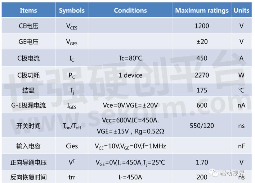
3.2 Application of IGBT in Vehicle Motor Controller
In the practical application environment of electric vehicles, due to the high power of the motor, the transient surge current of IGBT may reach more than 700A. We use two 2MBI450VN-120-50IGBT of Fuji Company for parallel output (the characteristic parameters of this IGBT are shown in Table 1), so that the output current of parallel IGBT can reach about 900A, which can meet the requirements of vehicle current. The electrical characteristic parameters of 2MBI450VN are shown in Table 1.
Table.1
In order to avoid the interference of stray distributed capacitance on the IGBT gate drive circuit, we directly weld the drive circuit board on the input pins of two IGBT modules, and connect the de-oscillating capacitance and bidirectional limiting circuit in parallel at the gate input terminals. If the IGBT is subjected to short-circuit current, it can be effectively protected if it can be turned off in time.
One of the ways to identify whether IGBT has overcurrent is to detect the voltage drop VCE of its tube.
When the IGBT is turned on, if VCE is too high, a short circuit will occur, and the IGBT should be turned off immediately.
When the IGBT is turned off by overcurrent, due to the large current amplitude in the IGBT, if the IGBT is turned off quickly, the Ldi/dt will be too high, and a high peak voltage will be generated at both ends of the IGBT, which will easily damage the IGBT, so the "soft slow turn-off" method is produced.
The M57962L drive circuit is designed according to the above theory.
When the IGBT is overloaded or short-circuited, the collector potential of the IGBT rises, and the current flowing into the detection circuit through the external diode increases. The gate turn-off circuit acts to cut off the gate drive signal of the IGBT, and at the same time, a low-level "overload/short-circuit" indication signal is output at the "8" pin.
Fig. 7 shows the waveforms of voltage and current when the IGBT is turned on and off. It can be seen from the figure that with the increase of gate voltage, its C-pole current rises, while VCE voltage drops. When the IGBT is turned off, the gate voltage is negative, the C-pole current drops, and VCE voltage rises to the power supply voltage.
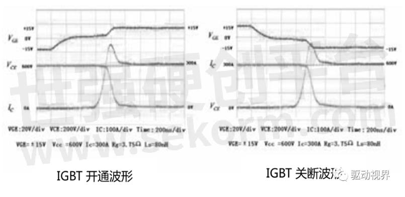
Figure 7 IGBT Turn-off voltage and current waveform diagram
4. conclusion
Based on the practical application, this paper expounds the design idea of IGBT module drive circuit of electric vehicle motor controller, summarizes the characteristics of IGBT module, the design and protection of gate drive circuit, the problems and protection methods of current, voltage and temperature protection of IGBT module in normal operation, and provides the corresponding design principle and verification scheme.
The actual verification proves that this circuit is reliable, practical, safe, and can be widely used in the design of motor controllers of various large-scale electric vehicles, and has a great application prospect.
[references]
[1] Wang Yingli, Du Ming, et al. extract parasitic parameters of bonding wires in IGBT modules [J] Chemical Automation and Instrument 2014 ,41 (4) 419-422
[2] Code for design of IGBT gate drive [N/OL]http://www.docin.com/p-374404232.html
[3] Fuji IGBT Module Application Manual of Fuji Electric Co., Ltd.[M]. 2011 09
[4] Hu Man-hong, Wang Ya-qiong's influence of parasitic capacitance on the change rate of collector voltage in IGBT switching process [N] Journal of Xinxiang Normal College2007.9 45-47
[5] Zhang Jun, Bian Qing, Design of Inverter Drive Circuit Based on IGBT [J] Automation Technology and Application2011.30.3 103 -105
[6] Jiang Wenqu Changmeng An IGBT Thick Film Circuit M57962L [J] Online http://www.paper.eud.cn
[7] Driving and Protection Technology of IGBT for Motor Controller of Sunny Yangjiangming Electric Vehicle[N/OL] http://www.docin.com/p-539436665.html
- |
- +1 赞 0
- 收藏
- 评论 0
本文由三年不鸣转载自SLKOR News,原文标题为:Driver technology of the new energy vehicle motor controller IGBT module,本站所有转载文章系出于传递更多信息之目的,且明确注明来源,不希望被转载的媒体或个人可与我们联系,我们将立即进行删除处理。
相关推荐

【经验】MOS管导通电流方向及MOS管体二极管最大极值分析
本文SLKOR主要就以下两个问题展开介绍:1、MOS管导通电流能否反着流?D到S,S到D方向随意?2、MOS管体二极管能过多大的电流?

【经验】一文介绍IGBT单管与IGBT模块的区别
本文SLKOR介绍IGBT单管与IGBT模块的区别,IGBT模块可以看作是IGBT单管的功能改进和升级,它们的应用领域基本相同。但是,由于集成了各种驱动和保护电路,IGBT模块的安装极大地方便了用户。随着新包装技术的采用,拓展了IGBT的应用领域。

【经验】一文解析MOS管的源极和漏极的区别
源极简称场效应管,T仅是由多数载流子参与导电,与双极型相反,也称为单极型晶体管。漏极利用外部电路的驱动能力,减少IC内部的驱动,或驱动比芯片电源电压高的负载。本文SLKOR将介绍MOS管的源极和漏极的区别。

MOS管用途?——放大作用、开关作用、保护作用、信号调制作用、电源控制作用
MOS管在电子技术中具有广泛的应用,包括放大作用、开关作用、保护作用、信号调制作用、电源控制作用。

SL27501 Series 35V 4A SiC 和 IGBT 8-引脚集成负压偏置驱动器
SL27501系列是Silicon Labs推出的35V 4A SiC和IGBT集成负压偏置驱动器,旨在为SiC MOSFET和IGBT提供高效的栅极驱动控制。该产品具有内置的负压生成、退饱和/短路保护和UVLO设置,支持TTL和CMOS兼容输入,适用于多种工业应用。
SLKOR - SIC 和 IGBT 8-引脚集成负压偏置驱动器,单通道高速智能驱动器,SL27501S,SL27501SE,SL27501,SL27501 SERIES,EV逆变,逆变器,充电站,不间断电源,PV 升压,EV 车载充电器,UPS,AC/DC 变换器,HEV 逆变,DC/DC 变换器

【产品】N沟道中压MOS管SL15N10A可承受高达100℃的工作温度,适用于高功率电路
SL15N10A是N沟道中压MOS管 ,漏源电压(Vdss)为100V,连续漏极电流(Id)为15A,导通电阻(RDS(on)@Vgs,Id)是130mΩ@20V,15A,阈值电压(Vgs(th)@Id)是20V@15A,具有高漏源电压和低导通电阻的特点,能够承受高达100℃的工作温度,可以广泛应用于各种开关电路、电源管理和电动机控制等领域。

碳化硅MOS管(SiC-MOSFET)的特征
本文通过与Si功率元器件的比较,来说明SiC-MOSFET的耐压范围。

萨科微碳化硅MOS管性能如何?——具有优异的电气特性和高温环境下的稳定性
萨科微的碳化硅(SiC)MOS管的确具有许多优异的特性,使其在高性能和恶劣工作环境下的应用非常适合。

30V/8.5A的低压MOS管SLP240C03D,具备高功率和电流处理能力
萨科微半导体的低压MOS管SLP240C03D是一种N+P互补型MOS管,它的漏源电压为30V,连续漏极电流为8.5A。在Vgs为10V,Id为8.5A时,导通电阻为19mΩ,阈值电压为1.6V@250μA。它具备高功率和电流处理能力,能够承受较高负载和压力,为电路设计提供了更大的弹性和可靠性。

萨科微卖的好的MOS管有哪些?有2SK3018、2N7002E、BSS138、IRF540NS等型号
萨科微卖的好的MOS管有2SK3018、2N7002E、BSS138、IRF540NS、SL05N06Z等型号,本文讲述了它们各自的特点和应用。

60V/50A的N沟道MOS场效应管SL50N06D,具有高频率、大电流、抗冲击能力强等优点
SL50N06D是一款N沟道MOS场效应管,采用先进的Trench技术生产。其具有较高的漏源电压(60V)和连续漏极电流(50A),具有高频率、大电流、抗冲击能力强等优点。它在BLDC电机技术领域不仅能够提高电力传动系统的效率和性能,还能够实现更加智能化的控制,通过对电机相电流进行高精度调控,实现了电机的高效、平稳运行。

萨科微卖的好的IGBT有哪些型号?SL20T65K1/SL15T120FL/SL15T65FK
萨科微卖的好的IGBT有SL20T65K1、SL15T120FL、SL15T65FK等型号,这些型号都是比较常见的IGBT(绝缘栅双极晶体管),可用于高功率应用和电力电子设备中。本文简单描述它们的特点及应用。

【经验】解析如何选择最适合的MOS管驱动电路
MOSFET管是FET的一种(另一种是JFET),可以被制造成增强型或耗尽型,P沟道或N沟道共4种类型,但实际应用的只有增强型的N沟道MOS管和增强型的P沟道MOS管,所以通常提到NMOS,或者PMOS指的就是这两种。本文SLKOR主要解析如何选择最适合的MOS管驱动电路。

60V/60A的N沟道MOS管SL60N06,导通电阻11.5mΩ,能在微波频率范围实现快速开关和精确控制
Slkor萨科微SL60N06是一款具有60V漏源电压和60A连续漏极电流的N沟道MOS管,以其低导通电阻(11.5mΩ@10V,30A)和较低的阈值电压(4V@250μA)而著称。该MOS管高频特性优越,能够在微波频率范围内实现快速开关和精确控制,具有高频率响应能力,能够满足高频信号的处理和传输需求。

60V/3A的N沟道MOS管SL3N06,具有大功率处理能力,广泛应用于小家电等领域
Slkor萨科微SL3N06是一款具有60V漏源电压和3A连续漏极电流的N沟道MOS管,以其低导通电阻(90mΩ@10V,3A)和较低的阈值电压(3V@250μA)而著称。这些特性使得 SL3N06成为小家电应用中理想的开关和信号处理元件,尤其是在需要高效能和高精度控制的场合。

电子商城

现货市场


服务
定制液冷板尺寸5mm*5mm~3m*1.8m,厚度2mm-100mm,单相液冷板散热能力最高300W/cm²。
最小起订量: 1片 提交需求>
授权代理品牌:集成电路


授权代理品牌:分立元件


授权代理品牌:接插件及结构件


授权代理品牌:部件、组件及配件


授权代理品牌:电源及模块


授权代理品牌:电子材料


授权代理品牌:仪器仪表及测试配组件


授权代理品牌:电工工具及材料


授权代理品牌:机械电子元件


授权代理品牌:加工与定制


登录 | 立即注册
提交评论