The Knowledge of S-Parameters and the Frequency Domain

Overview
Physical layer test systems can provide measurement-based frequency domain information in two ways:
Making frequency domain measurements directly utilizing a vector network analyzer (VNA) and an S-parameter test set to sweep the DUT with an RF signal and measure the RF response.
Making the time domain measurements utilizing a Time Domain Reflectometer (TDR) to apply a synthesized step waveform to a DUT and observing the response. Then the measured time domain information is converted to the frequency domain using the Fast Fourier Transform (FFT).
In a linear network, the Fourier Transform describes the relationship between a time domain measurement and its corresponding frequency domain response in detail. Therefore, given the measured time domain response of a DUT, it is possible to determine its frequency domain response mathematically by performing a Fourier Transform.
There is information to be gained from the frequency domain that other analysis types do not provide. Frequency domain information can help you verify and validate your modeling and simulation procedures by providing:
Vector error-corrected data which allows you to de-embed fixtures and signal launches
More accurate simulation for frequency-dependent effects, such as bandwidth and impedance
Insight into common analog problems, such as crosstalk, reflections, and loss
Better information more efficiently when you are analyzing the effects of transmission lines, studying power/ground distribution, and investigating EMI effects as a function of frequency
S-parameter data which can be used over the widest range of applications and frequency bandwidths
About S-Parameters
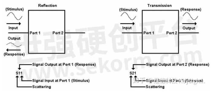
At high frequencies, S-parameters (scattering parameters) are commonly used to describe the performance of microwave and RF devices. These parameters can be used to completely describe the electrical behavior of the device (or network). For those not familiar with S-parameters, they are simply the energy that is reflected off of, or transmitted through, a device under test. While S-parameter data is formatted differently than TDR/TDT data, the underlying information is the same.
S-parameters relate to familiar measurements such as reflection coefficient (input/output match), and transmission coefficient (gain or loss, and isolation). They are the shared language between simulation and measurement and are easily imported into EDA tools like HSPICE, ADS, and other simulators.
Conventional single-ended parameters describe the performance of a single-ended device when it is stimulated on a single port, and the corresponding responses are observed on all of the ports. For a detailed explanation, refer to Single-Ended (Unbalanced) S-Parameters. Mixed-mode (or balanced) S-parameters describe the performance of devices with balanced ports. For a detailed explanation, refer to Mixed Mode (Balanced) S-Parameters.
Common Frequency Measurements with S-Parameters
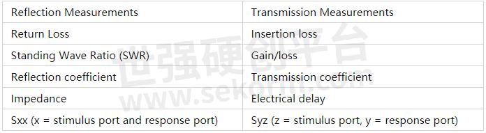
How to Interpret S-Parameters
A multi-terminal device can be viewed in different ways, depending on how it is meant to be operated. For a device that is designed to be a single-ended four-port device, its conventional (single-ended) four-port S-parameters can be measured and displayed. In a balanced device, two terminals constitute a single balanced port. Each balanced port will support both a common-mode and a differential-mode signal. This performance is described using mixed-mode (balanced) S-parameters.
Single-Ended (Unbalanced) S-Parameters
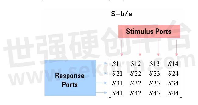
Conventional single-ended S-parameters are defined as the ratio of two normalized power waves (response/stimulus), defined in terms of the voltages and current at each port of a device. S-parameter notation identifies these quantities using the following convention:
SAB
where:
The first number (represented by A) refers to the test-device port where the signal is received. This received signal is referred to as the response.
- and -
The second number (represented by B) refers to the test-device port where the signal is sourced. This signal is referred to as the stimulus.
The following shows the naming convention for a single-ended 4-port S-matrix, showing the ratio of all possible combinations of response/stimulus.
Mixed Mode (Balanced) S-Parameters
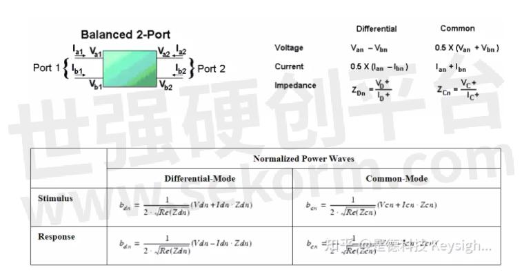
Mixed-mode S-parameters are used to describe the performance of balanced circuits by independently considering each mode of operation. The mixed-mode S-parameter concept is similar to conventional S-parameter definitions, except that instead of stimulating a single terminal of the DUT, we consider pairs of terminals to be stimulated in either a differential (anti-phase) or a common (in-phase) mode.
For a balanced device, we are not necessarily interested in voltages and current reference to the ground. Instead, we can define differential and common mode voltages and currents on each balanced port. Likewise, we can also define differential-mode and common-mode impedances.
We can define normalized power waves on the ports of a balanced device having the exact same form as the single-ended case. Only the definitions of "voltage" and "current" are changed. Both are defined as ratios of normalized power waves.
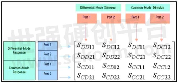
Mixed Mode Naming Convention
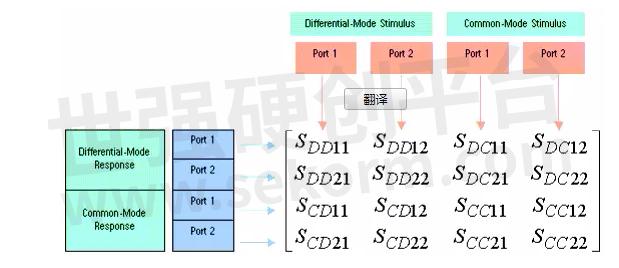
The naming convention for mixed-mode S-parameters includes mode information as well as port information. Unlike the single-ended example, though, in the mixed-mode S-matrix, we are not only considering the port, but we are also considering the mode of the signal at each port. Therefore, the first two subscripts describe the mode of the response and stimulus, respectively, and the next two subscripts describe the ports of the response and stimulus.
Again we can take the ratio of all possible combinations of response over stimulus for the differential and common mode normalized power waves to calculate the mixed-mode S-parameters. The mixed-mode matrix fully describes the linear performance of a balanced two-port measurement. The following shows the naming convention for a mixed mode S-matrix, showing the ratio of all possible combinations of response/stimulus.
S mode response, mode stimulus, port response. port stimulus
mode = Differential or Common
port = balanced port number (1 or 2)
- |
- +1 赞 0
- 收藏
- 评论 0
本文由剑藏锋转载自Keysight zhihu,原文标题为:S参数和频域 S-Parameters and the Frequency Domain,本站所有转载文章系出于传递更多信息之目的,且明确注明来源,不希望被转载的媒体或个人可与我们联系,我们将立即进行删除处理。
相关研发服务和供应服务
相关推荐

是德科技解析ADS软件的功能和用途
为了设计高性能的电路并评估其性能,工程师需要使用先进的设计和仿真工具,ADS就是比较主流的一个软件。那么ADS是什么软件?ADS软件是干什么的?下面介绍一下ADS软件的功能和用途。

如何在ADS中进行通道仿真
为了解决这些问题我们就必须采用一些均衡(EQ)措施,或者采用编码等方法。此外,由于处理的数据量增加,瞬态仿真非常的耗时间,这样看来瞬态仿真就显得力不从心了。为了解决上述问题,Keysight推出了通道仿真解决方案,学习如何在ADS中进行通道仿真,以及通道方针所涉及的一些问题。

如何在ADS中进行通道仿真?
在评估高速通道的性能时,过去经常采用瞬态仿真(Transient simulation)来查看接收端的时域特性,但是随着信号速率的不断增加,我们需要考虑的因素越来越多,或者说之前不起眼的因素会对我们的信号质量产生严重的影响。为了解决上述问题,KEYSIGHT推出了通道仿真解决方案,这篇文章就来学习如何在ADS中进行通道仿真,以及通道方针所涉及的一些问题。

是德科技的PathWave ADS仿真软件,可以轻松仿真PCB串扰,加速产品开发流程
是德科技的PathWave ADS仿真软件,可以轻松仿真PCB串扰,结合是德科技的网络分析仪和PLTS软件进行串扰的测试,可以完成从概念设计、仿真、原型机设计、验证到生产制造和部署的全流程管理,从而加速产品开发流程。

【经验】想要制作自定义的ADS设计套件吗?先来看看ADS原理图元件库的制作过程
ADS是工程师用于各种高频和高速电路与系统设计应用的主力工具,覆盖芯片,模块,板级设计,要使用该设计环境并利用其仿真功能,设计人员应具有链接到模型文件或仿真数据的元件库,设计套件即是以设计师为本的元件库工具包。本文介绍了自定义的ADS设计套件的过程。

【应用】Keysight ADS CILD和SIPro助力PCIE 5.0设计layout前后验证
本文主要介绍了PCIE 5.0主要指标、PCIE 5.0 设计面对的挑战、应对PCIE5.0设计挑战和PCIe 5.0仿真实例;突出了是德科技在开发中所提供的完美解决方案优势,针对于PCIE 5.0 设计面对的挑战,在Keysight ADS中,CILD和SIPro两个工具,可以分别满足PCIE 5.0 设计 layout前后的验证要求。

ADS与PCB协同仿真?是德科技的ADS软件成最主流的仿真工具
在进行射频PCB电路设计的时候,我们一般靠“经验”和“原则”指导设计,某些情况经验的作用也是有限的。要设计好射频板级电路,仿真是必不可少的。之所以某些经验可以替代仿真,是因为产品的电路非常成熟或集成化程度较高,对于创新型的设计,单纯依赖经验往往是不够的。科学的方法是将PCB封装和元器件仿真模型进行Co-Simulation半实物仿真,是德科技的ADS软件是最主流的仿真工具。

【应用】Keysight ADS提供通用的PAM4 PRBS源和TX/RX模型助力光模块设计与仿真
Keysight ADS提供通用的PAM4 PRBS源和TX/RX模型助力光模块设计与仿真技术,本文介绍了高速光模块的电路设计与仿真。


是德科技解析ADS软件和射频电路仿真
Keysight PathWave先进设计系统(ADS)通过将互连电路设计软件的模块――包括射频集成电路(RFIC)、单片微波集成电路(MMIC)、层压板、晶圆级封装、天线和印刷电路板(PCB)――智能集成到密集的3D结构中,可以大幅减少代价高昂的硬件故障。根据具体应用,您应该选择合适的软件。

如何用ads软件仿真doheerty功放?
针对高峰均比调制信号,Doherty功放架构可以实现更高的效率。设计Doherty功放,需要根据功放管负载牵引模型找到其主路,辅路的最佳阻抗点。由于负载牵引数据量较大,处理较为繁琐,本文使用ADS Datalink模板帮助工程师快速寻找最佳阻抗点。PathWave先进设计系统针对高峰均比调制信号,Doherty功放架构可以实现更高的效率。

Keysight Streamline系列USB矢量网络分析仪P937XA 2端口,最高26.5 GHz数据表
型号- P9370A,P937XA SERIES,P9372A,P9371A,P9374A,P9373A,P9375A,P937XA

VNA Simplifies Wideband Demodulation
This blog discusses how to measure an amplifier’s EVM using only a vector network analyzer (VNA) and how to use the VNA’s signal analysis application to capture the amplifier’s EVM to a given constellation and demodulation standard.

【经验】电源传输网络传导骚扰设计——如何使用ADS PIPro优化
ADS PIPro全新的CEMI插件,可以很好地解决CE的仿真挑战,提供虚拟测试拓扑和方便易用的开关电源模型,在时域和频域对电源传输网络的传导骚扰行为进行查看和优化,助力更快更好的完成电源传输网络的设计。

电子商城


现货市场

服务
提供是德(Keysight),罗德(R&S)测试测量仪器租赁服务,包括网络分析仪、无线通讯综测仪、信号发生器、频谱分析仪、信号分析仪、电源等仪器租赁服务;租赁费用按月计算,租赁价格按仪器配置而定。
提交需求>
朗能泛亚提供是德(Keysight),罗德(R&S)等品牌的测试测量仪器维修服务,包括网络分析仪、无线通讯综测仪、信号发生器、频谱分析仪、信号分析仪、电源等仪器维修,支持一台仪器即可维修。
提交需求>
授权代理品牌:集成电路


授权代理品牌:分立元件


授权代理品牌:接插件及结构件


授权代理品牌:部件、组件及配件


授权代理品牌:电源及模块


授权代理品牌:电子材料


授权代理品牌:仪器仪表及测试配组件


授权代理品牌:电工工具及材料


授权代理品牌:机械电子元件


授权代理品牌:加工与定制


登录 | 立即注册
提交评论