How to Transition from Designing for Microwave Frequencies to Millimeter-Wave Frequencies


Bandwidth is being consumed everywhere, in electronic vehicles and by 5G cellular wireless communications networks. While it may be becoming thinner at lower frequencies, it is still available at higher frequencies, at millimeter wavelengths. These correspond to a range of 30 to 300 GHz, often starting at 24 GHz in vehicular radar systems, and many microwave circuit designers are faced with the task of moving higher in frequency and developing millimeter-wave printed circuit boards (PCBs). They need to design and fabricate the finer circuit features needed for the smaller wavelengths of millimeter-wave frequencies, making a transition from microwave to millimeter-wave frequencies. Higher frequency PCBs require a thoughtful choice of circuit materials well suited for millimeter-wave frequencies and circuit fabrication processes that support those higher frequencies. Part 1 of this blog will explore circuit material characteristics that make them best suited for millimeter-wave frequencies. Part 2 will examine high frequency structures and the fabrication processes that can help them do best at millimeter-wave frequencies.
Millimeter-wave PCBs were once considered esoteric or, at the very least, solely the foundations of military/aerospace applications. Large numbers of wireless communications users below 6 GHz and the large amounts of data they generate are congesting microwave frequency airwaves and cultivating strong interest in the use of higher frequencies. While the first four generations of cellular wireless communications networks have performed reliably at microwave frequencies, the Fifth Generation (5G) is looking to millimeter-wave frequencies for sufficient bandwidth for high speed, short-range data links. In addition to personal wireless communications, 5G networks will support countless sensors, identification, monitoring, and surveillance devices. And automakers are relying on Advanced Driver Assistance System (ADAS) equipment including short-range radars operating at millimeter-wave frequencies for safer vehicles. Demands are growing for millimeter-wave circuits and with them the need for dependable circuit materials.
Material Qualities
Circuit designers face numerous changes when making a transition from microwave to millimeter-wave frequencies. Wavelengths continue to shrink as frequencies rise, requiring finer circuit structures. Also, signal power—generating it and maintaining it—is typically less at millimeter-wave frequencies than at microwave frequencies, so that low circuit loss is a key circuit design goal. Without considering the type of circuit structure, such as microstrip, stripline, substrate integrated waveguide (SIW), or grounded-coplanar-waveguide (GCPW) transmission lines at millimeter-wave frequencies, circuit materials for millimeter-wave circuits should be considered for whether they have optimal basic qualities, such as dielectric constant (Dk) and dissipation factor (Df), for circuits and applications making a transition to higher frequencies. A circuit material’s Dk is related to the real component of the material’s complex permittivity while its Df or loss tangent is related to the imaginary component of the material’s complex permittivity. These and other essential circuit material qualities can provide invaluable insight into how a circuit laminate will perform at millimeter-wave frequencies compared to microwave frequencies.
For example, many applications, such as automotive radar systems, require consistent, stable signal phase at millimeter-wave frequencies, such as 77 GHz. A circuit material well suited for millimeter-wave circuits would leave no trace of its own on a circuit’s phase response or the way that signals propagate through its metal conductors. For this type of performance at millimeter-wave frequencies, a circuit material must have minimal change or variation in Dk value. Even small Dk deviations, if they can be accurately measured, can result in variations in signal propagation and phase through a millimeter-wave transmission line.
A circuit material’s Dk is typically determined by fabricating a reference circuit on the material under test and measuring phase for different lengths of transmission lines at different test frequencies. The test frequencies and the phase lengths of the transmission lines correspond to Dk values which are then associated with that dielectric material and thickness and that measured thickness of laminate metal.
For the small wavelengths of millimeter-wave signals, and depending upon the transmission-line format, circuit materials with low, stable Dk values (such as about 3.0) support many higher frequency circuits with minimal variations in the signal phase. Variations in Dk within the material should be minimized to minimize signal phase variations. Again, the amount of impact that a circuit material’s Dk variations will have at millimeter-wave frequencies will depend upon the type of circuitry and transmission lines. Some circuit configurations are well suited for standard circuit fabrication processes but may not support all the small circuit features needed at millimeter wavelengths. A transition from microwave to millimeter-wave circuits represents a choice of circuit laminate as well as transmission-line technology for the best results.
Another basic circuit material quality to be considered when specifying a circuit material for the millimeter-wave frequency range is Df or loss tangent, often referred to as just its loss. Low Df values are usually associated with low Dk values and, as with Dk, low Df values are preferred for circuit materials to be used for millimeter-wave circuits. Similarly, as Dk variations can degrade a circuit's phase response at millimeter-wave frequencies, a circuit material’s Df variations can impact a circuit's amplitude response as a function of frequency, with loss increasing with increasing frequency. For any circuit at millimeter-wave frequencies, a choice in circuit technology should be part of a choice in circuit material since some transmission-line technologies will be less affected by variations in Dk and Df than others. However, as Part 2 of this blog will explain, some transmission-line technologies are better suited to handling the process variations that can be encountered when fabricating millimeter-wave circuits on even the best circuit laminates.
Several additional circuit material properties help guide specifiers to circuit laminates for millimeter-wave circuits. The surface roughness of the copper at the copper/dielectric interface of a laminate can limit millimeter-wave circuit performance if excessive. The increased loss and variations in the signal phase will depend on operating frequency and type of transmission line. For microstrip (Fig. 1), smoother copper is better: circuit laminates with rougher copper surfaces suffer increased conductor (insertion) loss and phase variations than the same dielectric materials and material thicknesses with smoother copper surfaces.

Fig 1. This cross-sectional view of a microstrip circuit exaggerates the roughness of the copper surface at the interface with the dielectric material.
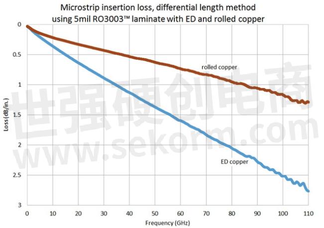
For microstrip, the effects of copper surface roughness are greatest for thinner circuit materials (Fig. 2). The effects can be minimized with thicker dielectric materials, although doing so will increase the circuit sensitivity to dielectric losses for those microstrip circuits.

Fig 2. Measurements on 5-mil-thick RO3003™ laminates from ROGERS Corp. show that differences in conductor types and copper surface roughness make differences in loss through 110 GHz.
Copper conductor surface roughness impacts millimeter-wave circuits especially as they are used for higher frequencies since the skin depth of an electromagnetic (EM) wave decreases with increasing frequency. The greatest degradation in amplitude and phase occurs when the skin depth of an EM wave is close to or less than the dimensions of the copper conductor surface roughness, generally the case at millimeter-wave frequencies. Circuit materials are available with different types of copper, each with its own amount of surface roughness. High profile copper is the roughest, with the greatest amount of impact on a millimeter-wave circuits loss and phase performance, while rolled copper is the smoothest, with the least amount of impact. In between, reverse treated (RT) copper and electrodeposited (ED) copper laminates provide surface roughness values that serve as midway points for their effects on loss and phase.
Rougher copper surfaces also result in a higher effective Dk value, or the Dk that a circuit “sees,” for material, as does thicker copper with certain designs, such as GCPW. A higher effective Dk will slow the propagation of an EM wave, causing phase variations in millimeter-wave circuits and timing variations in high-speed digital circuits. For that reason, the surface roughness and thickness of a copper laminate should be considered when a design is based on a circuit material with a particular effect or “design” Dk value, as the values of the copper thickness and its surface roughness, and variations in those values across the circuit material, can introduce unwanted performance variations especially at millimeter-wave frequencies. The effects of copper thickness and surface roughness are less for circuit materials with thicker dielectric materials than for those with thinner dielectric materials.
- |
- +1 赞 0
- 收藏
- 评论 0
本文由董慧转载自Rogers,原文标题为:How to Transition from Designing for Microwave Frequencies to Millimeter-Wave Frequencies,本站所有转载文章系出于传递更多信息之目的,且明确注明来源,不希望被转载的媒体或个人可与我们联系,我们将立即进行删除处理。
相关推荐
Rogers‘ Advanced Laminates Power The Mars Exploration of NASA
NASA announced yet another historic moment on Mars: the landing of their most advanced explorer yet, the Perseverance Rover. High-frequency specialty laminates enable radars and antennas on these types of rovers and the vehicles that get them there. The advanced circuit materials of ROGERS have been in nearly every US space mission,such as Rogers RT/duroid® high frequency circuit materials are filled PTFE (random glass or ceramic) composite laminates for use in high reliability, aerospace and defense applications.
ROGERS Provides Various of Circuit Laminates in Reliable PTFE, Creating Possibilities for Improved Performance
Composite materials for circuit materials are carefully researched for electrical and mechanical behavior under many different environmental conditions and knowing how the different ingredients of a circuit material work together can often ease the task of finding the best circuit material for a particular application.
ROGERS层压板/高频板选型表
罗杰斯/ROGERS提供以下技术参数的层压板/高频板选型,超低损耗,低至0.0004(Df) ;超大尺寸:54inchX24inch、52inchX40inch、50.1inchX110inch 等;丰富介电常数:2 -12.85 (Dk);超薄介质,低至1mil
|
产品型号
|
品类
|
产品系列
|
介电常数(Dk)
|
正切角损耗(Df)
|
介质厚度(mm)(mil)
|
导热系数W/(m·K)
|
铜箔类型
|
铜箔1厚度
|
铜箔2厚度
|
尺寸(inch)
|
|
5880LZNS 24X18 H1/H1 R4 0100+-001/DI
|
层压板
|
RT/duroid® 5880LZ
|
2
|
0.0027
|
0.254mm(10mil)
|
0.33
|
电解铜
|
H1
|
H1
|
24X18
|
选型表 - ROGERS 立即选型
产品变更通知:RO3003™层压板PTFE树脂供应商变更
Rogers Corporation宣布,RO3003™汽车修订版层压板将更换PTFE树脂供应商。新供应商的RO3003层压板样品预计于2023年8月从苏州中国制造工厂提供,比利时根特工厂的样品预计于2023年第四季度提供。公司已测试新供应商的PTFE树脂与现有树脂的对比,分析显示两者性能无显著差异。用户可根据自身需求评估产品适用性,并提供免费样品。
ROGERS - 层合板,LAMINATES,RO3000® SERIES,RO3003,RO3000,RO3003™,RO3000®
TMM®系列层压板产品安全信息表
本资料为TMM系列层压板的物质安全信息表,由Rogers Corporation提供。资料详细介绍了该产品的成分、危害识别、急救措施、消防措施、泄漏处理、操作与储存、暴露控制与个人防护、物理和化学性质、稳定性与反应性、毒理学信息、生态信息、处置考虑、运输信息、法规信息及其他信息。资料强调,该产品在正常使用条件下不会释放有害化学物质,因此无需提供安全数据表。
ROGERS - LAMINATES,层合板,99043,TMM SERIES,TMM,TMM® SERIES,TMM®
Rogers(罗杰斯) RO4233 LNB Laminates数据手册
本资料为Rogers Corporation生产的RO4233™ LNB覆铜基板的数据表。内容包括材料的电学、力学、热学和物理性质,以及与加工相关的标准厚度、尺寸和铜箔涂层的详细信息。
ROGERS - LNB LAMINATES,LNB层板,微波电路板材,4233 48X36 5E/5E 0900+-004/DI,RO4233™,RO4000,RO4233碳氢化合物陶瓷,4233LN 48.25X36.25 5E/5E 0200+-0015/DI,4233 24X18 1E/1E 0200+-0015/DI,4233 24X18 5E/5E 0900+-004/DI,4233 24X18 5E/5E 0200+-0015/DI,室内照明,机车,工业设备控制,车载娱乐,车载,电力,车身和底盘,照明,车联网,手机相关,电动汽车动力系统,通信设备,车载通讯,装备及逆变电源,可再生能源,工业自动化,工业伺服,智能家居,轨道交通,国防工业设备,物联网,仓储,安全系统
TC Series™层压板聚四氟乙烯复合材料产品安全信息表
本资料为TC系列覆铜板的产品安全信息表,由Rogers Corporation提供。资料详细介绍了该产品的成分、危害识别、急救措施、消防措施、事故泄漏处理、操作与储存、暴露控制与个人防护、物理和化学性质、稳定性与反应性、毒理学信息、生态信息、处置考虑、运输信息、法规信息及其他信息。资料强调,正常使用下该产品不会释放有害化学物质,因此无需安全数据表。
ROGERS - LAMINATES,层合板,TC SERIES™,TC,印刷电路板,PRINTED CIRCUIT BOARDS
苏州工厂设备预防性维护保养计划通知—仅限覆铜基板(Notice of Planned Preventative Maintenance Rogers Suzhou Manufacturing Facility – Laminates Only)
罗杰斯公司苏州工厂计划于2024年9月30日至10月16日进行为期16天的设备预防性维护保养,以提升设备性能和可靠性。在此期间,10月1日至7日为中国的法定假日。公司评估认为,目前预测显示此维护保养不会影响现有标准交期,但若出现未预见的需求增加,可能导致交期延长。公司请求客户在9月9日前提供至10月第二周的需求订单,以便提前安排备货和生产。罗杰斯公司感谢客户的耐心和支持,并承诺提供高质量产品和服务。
ROGERS - 覆铜基板,LAMINATES,层合板
RT/Duroid®5870-5880层压板
本文介绍了RT/duroid® 5870-5880玻璃微纤维PTFE复合材料的介电常数各向同性的优势。与传统编织织物增强复合材料相比,该材料在介电常数的各向同性方面具有显著优势,特别是在高频电路设计中,有助于简化计算并提高性能。
ROGERS - LAMINATES,层合板,RT/DUROID 5870,RT/DUROID® 5880,RT/DUROID® 5870
AD1000™层压板数据手册
本资料介绍了AD1000™微波印刷电路板用PTFE/玻璃纤维/陶瓷填充层压材料。该材料具有高介电常数,适用于小型化电路设计,特别适合功率放大器、滤波器、耦合器和低阻抗线组件。它提供了比传统低损耗材料更小的尺寸稳定性,并具有良好的机械强度和热膨胀系数,适用于紧凑型设备、卫星通信系统、雷达模块等多种应用。
ROGERS - 编织层压板,陶瓷填充层压板,FIBERGLASS LAMINATE,机织玻璃纤维增强层压板,WOVEN LAMINATE,PTFE层压板,LAMINATES,WOVEN-GLASS REINFORCED LAMINATE,PTFE LAMINATE,CERAMIC FILLED LAMINATE,层合板,玻璃纤维层压板,AD1000,AD1000™,RADAR MANIFOLDS,贴片天线,POWER AMPLIFIERS (PAS),雷达管汇,低噪声模块下变频器(LNB),低噪声放大器,GPS接收机,AIRCRAFT COLLISION AVOIDANCE SYSTEMS(TCAS),LOW NOISE BLOCK DOWN CONVERTERS (LNBS),地面雷达监视系统,COMPACT DEVICES,雷达模块,MICROWAVE PRINTED CIRCUIT BOARDS,飞机防撞系统(TCAS),SATELLITE COMMUNICATIONS SYSTEMS,功率放大器(PAS),LOW NOISE AMPLIFIERS (LNAS),GPS RECEIVERS,紧凑的设备,卫星通信系统,RADAR MODULES,GROUND BASED RADAR SURVEILLANCE SYSTEMS,PATCH ANTENNAS,微波印刷电路板
Rogers Corporation RO3000®层压板PTFE分散体供应商更改RO3210™层压板数据比较
Rogers Corporation发布了一份关于其RO3210™层压板的性能数据比较报告,比较了使用传统和新型PTFE分散供应商生产的层压板的各项性能。报告显示,两种供应商生产的层压板在介电常数、损耗因子、铜剥离强度和吸湿率等关键性能指标上没有显著差异。
ROGERS - LAMINATES,层合板,RO3210™,RO3000®
RO4000®系列层压板产品安全信息表
本资料为RO4000®系列层压板热固性复合材料的安全信息表。内容包括物质/制剂的识别、危害识别、成分信息、急救措施、消防措施、意外泄漏处理、处理和储存、暴露控制/个人防护、物理和化学性质、稳定性和反应性、毒理学信息、生态信息、处置考虑、运输信息、法规信息和其它信息。资料详细描述了该产品的安全使用和处理方法,以及可能产生的危害和应对措施。
ROGERS - LAMINATES,层合板,RO4000 SERIES,RO4000®,RO4000,RO4000® SERIES,印刷电路板,PRINTED CIRCUIT BOARDS
TMM®层压板数据表
TMM®热固性微波材料是一种陶瓷、碳氢化合物和热固性聚合物复合材料,适用于高可靠性通孔印刷电路板(PCB)基材。这些材料具有广泛的介电常数范围,结合了陶瓷和传统PTFE微波电路覆铜板的许多优点,同时无需采用这些材料的专用生产技术。TMM覆层在制造和组装过程中减少了对材料的损害,提供了可靠的焊接性能,并且不需要特殊的生产工艺。
ROGERS - LAMINATES,层合板,TMM10,TMM10I,TMM13I,TMM,TMM6,TMM4,TMM3,TMM®,GLOBAL POSITIONING SYSTEMS ANTENNAS,贴片天线,LENSES,过滤器,组合器,功率放大器,芯片测试仪,DIELECTRIC POLARIZERS,COUPLER,镜头,微波电路,RF CIRCUITRY,SATELLITE COMMUNICATION SYSTEMS,耦合器,MICROWAVE CIRCUITRY,全球定位系统天线,介质偏振器,FILTERS,CHIP TESTERS,POWER AMPLIFIERS,COMBINERS,射频电路,卫星通信系统,PATCH ANTENNAS
Kappa™层压板产品安全信息表
本资料为一份产品安全信息表,针对名为KappaTM Laminates的热固性复合材料。资料内容包括产品标识、危害识别、成分信息、急救措施、消防措施、意外泄漏处理、操作与储存、暴露控制与个人防护、物理和化学性质、稳定性和反应性、毒理学信息、生态信息、处置考虑、运输信息、法规信息和其他信息。资料强调了正常使用情况下该产品不会释放有害化学物质,因此无需安全数据表。
ROGERS - 热固性复合材料,THERMOSET COMPOSITE MATERIALS,LAMINATES,层合板,KAPPA™,印刷电路板,PRINTED CIRCUIT BOARDS
RT/Duroid®5880层压制品安全信息表
本资料为RT/Duroid™5880层压板的物质安全信息表。内容包括产品标识、危害识别、成分信息、急救措施、消防措施、意外泄漏处理、操作与储存、暴露控制与个人防护、物理和化学性质、稳定性与反应性、毒理学信息、生态信息、处置考虑、运输信息、法规信息及其他信息。资料强调正常使用下无危害,但加工过程中可能产生粉尘,需注意防护。
ROGERS - LAMINATES,层合板,RT/DUROID® 5880,RT DUROID 5880
电子商城
品牌:ROGERS
品类:Circuit Materials
价格:¥2,479.9453
现货: 1,211
品牌:ROGERS
品类:High Frequency Circuit Materials
价格:¥550.8681
现货: 4,126
品牌:ROGERS
品类:Antenna Grade Laminates
价格:¥2,989.4355
现货: 429
品牌:ROGERS
品类:High Frequency Circuit Materials
价格:¥554.2134
现货: 335
品牌:ROGERS
品类:Liquid Crystalline Polymer Circuit Material
价格:¥1,485.0299
现货: 253
品牌:ROGERS
品类:Antenna Grade Laminates
价格:¥2,571.9097
现货: 250
品牌:ROGERS
品类:High Frequency Circuit Materials
价格:¥2,669.6313
现货: 250
品牌:ROGERS
品类:PTFE/Woven Fiberglass Laminates
价格:¥16,030.1502
现货: 201
品牌:ROGERS
品类:Antenna Grade Laminates
价格:¥4,406.0729
现货: 175
服务
使用FloTHERM和Smart CFD软件,提供前期热仿真模拟、结构设计调整建议、中期样品测试和后期生产供应的一站式服务,热仿真技术团队专业指导。
实验室地址: 深圳 提交需求>


登录 | 立即注册
提交评论