Radar transceivers: a key component for ADAS & Autonomous Driving-Basics of FMCW radar


1.1 What is radar?
Radar (acronym for Radio Detection and Ranging) uses radio waves to detect objects in the environment. It allows determining the distance (known as range), angular position (bearing), and velocity. Radar technology was developed for military use during World War II, but has now many civil applications, including air or marine traffic control, astronomy, ocean and meteorological monitoring, altimetry, geological observations and automotive applications.
The radar system includes a transmitter, which emits an electromagnetic radiofrequency wave (radar signal) in a certain direction. The signal reflected off the target objects (echo) is then detected by the radar receiver. The magnitude of the reflection is determined by the object’s material properties, size and shape (radar cross section RCS). By processing this reflected signal, the properties of the target can be determined.
1.2 FMCW radar
Automotive radar systems operate using a so-called Frequency Modulated Continuous Wave (FMCW). The system transmits a continuous wave at a certain frequency, which is then modulated over a period of time T. This gives the transmitted signal a “time stamp". The signal travels then to the target and part of it is reflected back. The radar will detect the reflected signal and compare it to the original one by mixing them and processing the resulting signal. A simplified schematic is presented in Figure 1.

Figure 1: FMCW automotive radar – Principle and building blocks
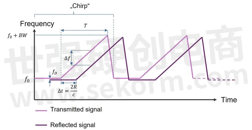
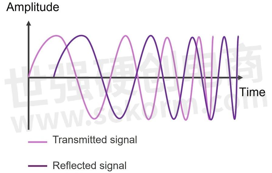
An example of this radar signal is shown in Figure 2 and Figure 3. The returned signal is similar in shape to the transmitted one, but shifted in time as the two-way trip from the radar to the target takes an amount of time ∆t that is proportional to the distance to the target R:

With c being the light velocity.

Figure 2: Sawtooth FMCW radar signal: frequency vs. time.

Figure 3: FMCW radar signal: amplitude vs. time.
By comparing the reflected wave with the original signal at any given moment of time, a frequency shift ∆f can be observed. This shift allows determining the range R for each period of the signal or “chirp”. If the signal is monitored over several chirps, an additional frequency shift fD will be detected for a target moving towards or away from the radar, due to the Doppler effect. This allows determining the velocity of the target. Finally, if different channels are considered, using spatially distributed antennas, the direction of arrival of the signal can be established, to obtain the 2D or 3D position of the target.
That means that, to have 4D detection (range, azimuth and elevation direction, and velocity), a space-time processing of the signal is needed. For that, the signal needs to be digitized and saved for further processing. The first step will be creating the so-called “radar cube”.
1.3 Radar processing - The radar cube
The radar data cube is three-dimensional graphic depiction of the space-time processing of the stored radar data. It summarizes the three basic steps required to obtain range, velocity and bearing information.
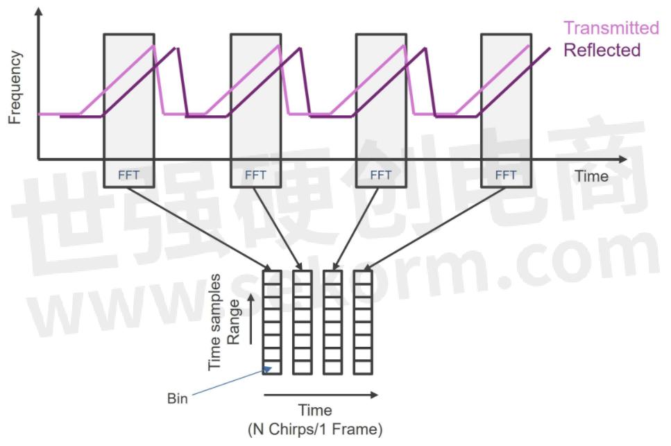
As mentioned above, the received signal is sampled for processing. The first step is performing an FFT (Fast Fourier Transformation) so that each sample corresponds to a “bin” to obtain the range information over the so-called “fast time”. This is illustrated in Figure 4. The procedure is repeated for each of the chirps that form a frame.

Figure 4: Radar processing: range FFT.
Once all the chips in a frame have been acquired, saved, and processed, the Doppler-FFT is performed to obtain information about the velocity of the target. This evaluation is done once per frame, i.e., every N chirps. Therefore, it is also known as “slow time”. Finally, the data from the spatial along all the available channels are combined, to get the third dimension of the radar cube, which contains the information on the spatial position of the target. The graphic representation of the radar cube is shown in Figure 5.

Figure 5: The radar cube.
1.4 Automotive radar modules
The deployment of automotive radar has been facilitated by the advances in the semiconductor technology, especially silicon based. While in the early 2010s multi-channel radar transceivers were integrated on a single GaAs (Gallium arsenide) MMIC (Monolithic microwave Integrated Circuits), nowadays the use of Silicon Germanium (SiGe) has increased the integration density and lowered the costs for mass production. The next challenge will be the transition to CMOS (Complementary metal–oxide–semiconductor), which will allow the integration of further digital circuits on the die while keeping good RF performance.
Yet, to implement a radar system, each radar module must include one or more MMICs transceivers, which emit the radar signal, detect the echoes from the obstacles and perform some signal conditioning and digitation to prepare the raw radar data for further analysis by a processing unit. The later can be a microcontroller unit (MCU) for basic processing, but with the advances in radar technology SoCs (System on Chip) are increasingly used to implement more sophisticated analysis, detection and tracking of the targets.
Figure 6 illustrates the different steps in the processing of the radar signals over the whole receiving path. While analogue RF processing and the conversion to digital signals are always performed on the MMIC, the interfaces for the signal analysis are not fixed. With increasingly complex radar architectures and signal processing, some steps such as the first FFT can already be performed on the MMIC. Moreover, it also possible to combine the radar transceiver and the processing unit in a single, monolithic chip for some applications like corner radars.

Figure 6: Radar processing steps.
In the future, more complex architectures could be implemented, with several satellite radars distributed around the car. The radar modules would then perform only a limited amount of pre-processing before delivering the data, e.g., range and point cloud, to a central control unit (ECU), which could then apply more advanced processing and data fusion, not only of the satellite radar modules but also of other sensors.
1.5 Conclusion
This entry has provided an overview of the operating principle of the FMCW radar, used in automotive applications, and its implementation using MMICs and MCU/SoC.
- |
- +1 赞 0
- 收藏
- 评论 0
本文由Batman转载自Renesas,原文标题为:Radar transceivers: a key component for ADAS & Autonomous Driving 2.- Basics of FMCW radar,本站所有转载文章系出于传递更多信息之目的,且明确注明来源,不希望被转载的媒体或个人可与我们联系,我们将立即进行删除处理。
相关研发服务和供应服务
相关推荐
【经验】关于瑞萨MCU RH850 C1M-A2的内存地址分配介绍
本文是关于瑞萨MCU RH850 C1M-A2的内存地址分配介绍,我们在设计瑞萨MCU RH850 C1M-A2的时候,对内存空间分布一定要有所了解。芯片内部flash和ram空间大小如下。
【经验】MCU RH850/F1K舵机PWM调试分享
PWM常常作为电机控制、舵机控制等使用,也是开发中最常用的控制方式。PWM实现需要使用定时器,RH850有非常多的定时器,并且可以配置很多通道,下面以瑞萨MCU RH850/F1K的TAUJ0定时器作为PWM定时器,实现PWM输出。
【经验】瑞萨RA系列MCU时钟系统解析
本文以瑞萨MCU RA6T2为例,如下XTAL是外接的主时钟,频率为8到24M范围内任意可选。连接到单片机的XTAL和EXTAL引脚,HOCO:是片上高速振荡器,他不可以随意设置,比如RA6T2,他的HOCO为16,18,20M三选一。
世强目前有代理riscv的mcu吗?
世强代理的RISC-V内核MCU厂家越来越多,还在不断增长。 国外厂家有瑞萨 【产品】瑞萨推出全新RISC-V MCU R9A02G020,优化先进电机控制系统设计和降低用户开发成本 国内厂家介绍如下: 广芯微内置32位RISC-V内核的PD SoC芯片UM3506,最高主频33MHz 全球首家全栈自研RISC-V内核的通讯接口芯片/全栈MCU供应商沁恒(WCH) RISC-V内核低功耗32位MCU,中移芯昇授权世强先进全线代理 芯昇科技携多款芯片产品亮相ICDIA,助力RISC-V生态发展 先楫半导体提供多系列通用MCU,以开源的RISC-V架构为核心,综合性能达世界领先水平 航顺芯片首次进入胡润全球独角兽榜,已量产中国第一颗M3+RISC-V多核MCU 中微半导体积极推动RISC-V架构安全化、智能化,共筑国产安全芯片生态 博流业界第一款基于RISC-V CPU的WI-FI+BLE双模SoC芯片,打造智慧家居AIoT芯片平台 璇玑CLE系列是核芯互联基于32位RISC-V内核推出的通用嵌入式MCU处理器 方寸微电子加入RISC-V产业联盟,推动安全芯片国产化,打破国外芯片技术垄断
瑞萨公开下一代车用SoC和MCU处理器产品路线图,全新R-Car MCU系列扩展其车辆控制产品阵容
瑞萨电子公开了针对汽车领域所有主要应用的下一代片上系统(SoC)和微控制器(MCU)计划。未来产品阵容包括采用先进小芯片封装(Chiplet)集成技术的R-Car SoC和基于Arm®核的车用MCU。
Renesas(瑞萨电子) R-Car M3车载SoC设备概述手册
描述- 本资料概述了Renesas Electronics的R-Car M3系列SoC的初步规格。R-Car M3具备下一代车载导航系统所需的基本功能,包括双核1.5GHz ARM Cortex-A57和四核1.3GHz ARM Cortex-A53核心、LPDDR4内存控制器、多种接口和图形处理单元。资料详细介绍了处理器、内存、显示、视频处理、音频接口、存储和网络等模块的规格和功能。
型号- R-CAR M3
【经验】SoC R CAR V3H2 cnn模型转换后执行以及benchmark过程实操指南
RENESAS SoC R CAR V3H2 cnn模型转换后的输出文件有bcl和.pb 2类,都是可以在端侧执行的,本文记录.pb的推理输出以及benchmark过程实操及解析。
瑞萨RX系列MCU实现二级MCU OTA升级:FreeRTOS篇
基于空中下载技术(OTA:Over-The-Air)并通过云服务端实现的MCU固件升级得益于云供应商和设备供应商之间的合作开展,目前已具备了简单且可快速部署的集成环境。瑞萨RX云互联解决方案开发团队开始提供即便在未直接与互联网连接的二级MCU中,也可以利用AWS IoT服务方案进行OTA固件升级的示例代码。
【产品】全新开放式平台,加大对ADAS及自动驾驶的支持
新型R-Car V3M SoC符合ISO26262功能安全标准,为视觉处理提供了低功耗硬件加速功能,还配有内置图像信号处理器。
RA系列MCU注入电流,防止损坏MCU应用笔记
描述- 本资料介绍了如何防止RA系列微控制器(MCU)因异常注入电流而损坏。内容包括推荐的注入电流条件、不同型号的参数限制以及额外的说明和建议,旨在指导用户在设计和应用过程中采取适当的措施以保护MCU免受损害。
型号- RA FAMILY,RA4T1,RA6T2,RA6T1,RA6T3,RA4M1,RA2L1,RA4M3,RA6M1,RA4M2,RA6M3,RA6M2,RA6M5,RA2E1,RA6M4,RA4E1,RA2E2,RA6E1,RA2A1,RA4E2,RA6E2
【应用】支持EtherCAT协议的瑞萨单芯片SoC用于伺服系统,实现实时响应,降低20%成本
在伺服系统的应用上,对于主控SoC的选择非常重要,Renesas SoC RZ/T1系列的R7S910025可以实现联网实时响应,采用ARM Coretex-R4F高实时性内核,自带FPU浮点运算单元,最高支持600MHz主频,达到962MIPS的运行速度。
【经验】基于瑞萨RH850/F1K的MCU 15833 CAN通信中断接收实现注意点
最近有客户在调试基于RH850/F1K的MCU CAN通信功能程序时,一直无法进入中断接收程序;经过查验总结问题所在点,步骤如下:1.在boot.asm文件,如果使用eiint作为表引用方法,启用下一行的宏。
【经验】SoC R CAR V3H2 CNN工具链转换restnet18 caffe模型为端侧可执行命令过程解析
RENESAS SoC R CAR V3H2 CNN工具链最主要的功能就是把caffe,onnx等模型转换为V3H2 芯片端可执行模型,命令,本文记录并分析此转换过程。
【经验】瑞萨RZ/T1 SoC芯片最小系统关于应用ΔΣ的IGBT波动干扰解决
很多客户使用了瑞萨RZ/T1的ΔΣ delta sigma,反馈IGBT波动有干扰。电源的干扰有可能对芯片的工作有影响,因为没有符合电源规范。变频的是MCU,电源可以+-20%呢,而rzt1是要求5%。 CPU没有出现异常,也可能是因为主频是450M,离600M还有很大的余量。本文介绍解决办法。
【经验】瑞萨MCU RL78 R5F10BGG FDL库调试指引
瑞萨MCU RL78由于其出色的性能和小体积(集成Data flash和高精度片上晶体),深受工程师喜欢,已成为很多小型设备开发首选。近期有客户在调试Data flash出现问题。
电子商城
现货市场
服务
可定制显示屏的尺寸0.96”~15.6”,分辨率80*160~3840*2160,TN/IPS视角,支持RGB、MCU、SPI、MIPI、LVDS、HDMI接口,配套定制玻璃、背光、FPCA/PCBA。
最小起订量: 1000 提交需求>
可烧录IC封装SOP/MSOP/SSOP/TSOP/TSSOP/PLCC/QFP/QFN/MLP/MLF/BGA/CSP/SOT/DFN;IC包装Tray/Tube/Tape;IC厂商不限,交期1-3天。支持IC测试(FT/SLT),管装、托盘装、卷带装包装转换,IC打印标记加工。
最小起订量: 1pcs 提交需求>


登录 | 立即注册
提交评论