How to Connect the Antennas


1. mmWave MMIC to antenna interfaces
We will focus on how to connect a monolithic microwave integrated circuit (MMIC) radar transceiver to the antennas in a way that guarantees an efficient transfer of the signals. At millimeter-wave (mmWave) frequencies, any transitions between two different transmission lines, on the chip, board, or antenna, can have a significant impact on the performance of the overall system. Any degradation or malfunction in the interfaces will cause signal loss or interference, leading to reduced performance or system failures. Therefore, one of the key challenges in the design of a radar module will be maintaining high signal integrity and low losses throughout the entire RF signal path between the MMIC and the selected antennas.
2. Chip to board BGA interface
t millimeter wave frequencies, chip-to-board transitions are challenging due to the short wavelengths involved. The most common approach is using the BGA to transfer the RF signals from the chip to a transmission line printed on the board, usually microstrip lines, but also striplines, coplanar waveguides (CPW) or substrate integrated waveguides (SIW) could be used. This allows a direct connection to on-board antennas, such as patch arrays.
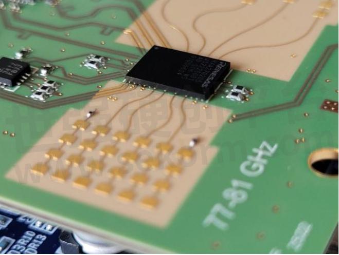
Figure 1: Radar MMIC to antenna connection through BGA interfaces
The transition structure needs to be designed to match the impedance of the MMIC to that of the transmission line on the board, to minimize losses and reflections. This is critical for efficient power transfer and optimal radiation efficiency and can be achieved by tapering the width of the line and/or adding matching structures.
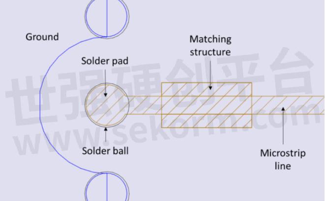
Figure 2: MMIC to board BGA interface with a matching structure
A careful design of the interface can help minimize the effect of crosstalk and interference, which can be significant at mmWave frequencies. It is also important to ensure good connection with the PCB ground, to further reduce interference and improve the signal-to-noise ratio.
High-quality, low-loss materials should be used for manufacturing the board, to reduce the losses on the transmission lines between the chip and the antenna. Additionally, special care must be taken during the assembly process, to ensure a proper alignment between the soldering balls and the lines, to avoid mismatching and minimize the parasitic effects.
Here again, use of electromagnetic simulation tools is capital to optimize the interface. The design must be adapted for the desired stackup and PCB layout, to guarantee the targeted performance is achieved. The simulation can be extended to include the antennas and, in the end, the whole PCB, and analyze the effects of material and manufacturing tolerances.

Figure 3: MMIC to board BGA interface – simulation model
3. Launcher on board for waveguide antennas
When 3D waveguide antennas are used, it is necessary to add a second transition, from the board to the antenna module. For that, the transmission line modes that carry the signal on the PCB (e.g. the microstrip quasi-TEM modes) have to be converted to waveguide modes.
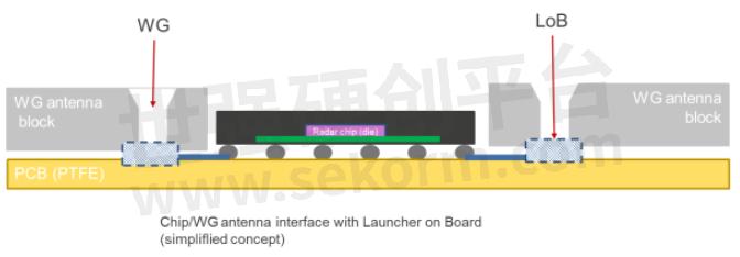
Figure 4: MMIC to waveguide antenna assembly with the launcher on board (LoB)
A waveguide launcher on board (LoB) is a small interface designed at the end of the PCB transmission line, which will provide a means for the electromagnetic waves generated by the radar MMIC to be coupled into the waveguide antenna. This can be a printed element (probe) or an aperture in a conducting plane.

Figure 5: Microstrip to waveguide transition – example concept

Figure 6: Waveguide slot antenna with microstrip feeding and launcher on board
The shape of the launcher on board must be optimized to maximize the coupling efficiency and to match the impedance of the transmission line on the board to the impedance of the waveguide. To ensure a smooth transition, tapered shapes are normally used. Indeed, sharp edges and abrupt discontinuities would cause high reflection levels, leading to power loss and signal distortion.
The size of the waveguide launcher is also of capital importance. It needs to be small enough to fit on the board, keeping the line lengths as short as possible. On the other hand, the laws of physics require that it be large enough to efficiently couple the signal from the PCB transmission line to the waveguide antenna. Here again, electromagnetic simulation tools are unavoidable to optimize the design of the launcher and accurately predict its performance.
High precision manufacturing and assembly will be required, to guarantee accurate contact and alignment between the board and the waveguide antenna. Any tolerances in the alignment or air gaps may lead to a high loss of performance.
4. Launcher on package for waveguide antennas
With a waveguide launcher on the package, the mmWave signals still need to be routed on the PCB. That means that high-quality, low-loss materials are required. This could be avoided with a direct coupling between the radar transceiver and the 3D antennas using a waveguide launcher in package (LiP), also known as Launcher on Package (LoP). The LiP/LoP is used to interface the MMIC with an external waveguide that feeds the antenna. It can be integrated into the package of the MMIC, avoiding the need for routing on the PCB, so that now lower-cost substrate materials can be used.
The package of the MMIC must be designed to accommodate a waveguide launcher for each transmit and for each receive channel of the radar transceiver. There are two options to implement the launcher in the package: top- or bottom-launch.
In a top-launch configuration, the antenna is placed on top of the package and will require mechanical support to guarantee the alignment and stability. The RF signals will be coupled to the waveguide without having to use any balls of the BGA.
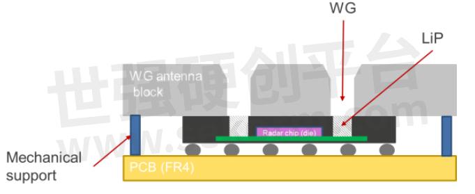
Figure 7: MMIC to waveguide antenna assembly with launcher in package (LiP) – Top launch
With the bottom-launch approach, the MMIC and the antennas are placed on opposite sides of the PCB. Some ball of the MMIC’s ball grid array (BGA) will be used to define the waveguide transition. The mmWave signals will be coupled to the antenna through a short waveguide defined by the BGA and plated holes on the PCB.
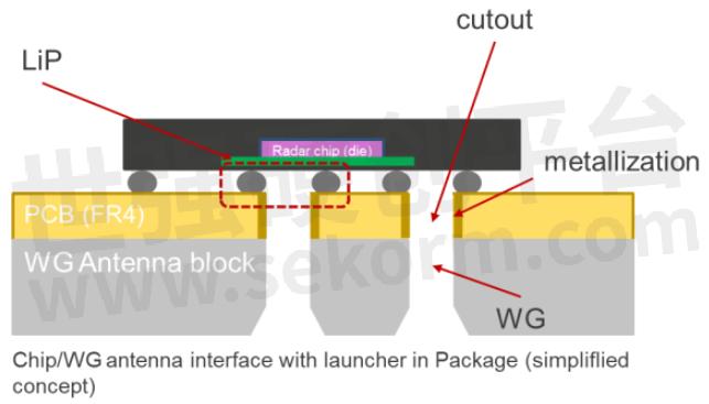
Figure 8: MMIC to waveguide antenna assembly with launcher in package (LiP) – bottom launch
In both cases, each launcher has a minimum size, dictated by the operating frequency, the overall size of the package will be increased with respect to that of the conventional BGA interfaces.
As in the case of the launcher on board, the launcher in the package needs to be designed to provide a smooth transition from the MMIC to the waveguide, minimizing the losses due to reflections and scattering, while matching the impedance of the chip to that of the waveguide.
The feeding network in the redistribution layers of the MMIC must be designed to provide a uniform distribution of power to each waveguide launcher while minimizing the coupling between the different RF ports. Also, the materials used in the packaging need to be carefully chosen, as they can affect the performance of the waveguide launcher.
The mechanical stability of the package with LiP is important for ensuring long-term reliability. The structure should be designed to withstand mechanical stresses and temperature variations. Also, it is capital to ensure the accurate alignment and proper contact between the launcher and the waveguide, to avoid not only loss of performance due to mismatch, but also to reduce the leakage which would cause increased coupling between the different RF channels.
- |
- +1 赞 0
- 收藏
- 评论 0
本文由翊翊所思转载自RENESAS Blogs,原文标题为:How to connect the antennas,本站所有转载文章系出于传递更多信息之目的,且明确注明来源,不希望被转载的媒体或个人可与我们联系,我们将立即进行删除处理。
相关推荐
How We can Increase the Accuracy of the Detection, Focusing on the Field of View, and the Range and Angular Resolution?
In the last entry of this blog Renesas will explain how we can increase the accuracy of the detection, focusing on the field of view, and the range and angular resolution.
【经验】用于汽车应用的FMCW雷达工作原理及如何使用MMIC和MCU/SoC实现
本篇文章Renesas概述了用于汽车应用的FMCW雷达工作原理及其使用MMIC和MCU/SoC的实现。
Radar transceivers: a key component for ADAS & Autonomous Driving-Basics of FMCW radar
This entry has provided an overview of the operating principle of the FMCW radar, used in automotive applications, and its implementation using MMICs and MCU/SoC.
可Pin to Pin 替换RichWave RTC6603SP的ISM频段射频开关SPDT uPG2214TB
Renesas公司的uPG2214TB是一款高性能,超小封装的ISM频段的单刀双掷射频开关(SPDT),采用砷化镓半导体工艺制造的单片式微波集成电路(MMIC),覆盖频率从50MHz到3.0GHz,通用性强, 可Pin to Pin 替换RichWave公司的RTC6603SP,且价格比RichWave RTC6603SP低10%。
Antennas for Automotive Radar
In previous issues of the radar blog, we have reviewed the main characteristics of MMIC transceivers for automotive radar. Yet, an aspect still needs to be covered: how to integrate the MMIC on the radar module’s PCB, and what should we consider to optimize the interface between the chip and the antennas.
Growth Strategies for Renesas Automotive Business in Emerging Regions and Emerging Segments
Thisarticle explains how Renesas will implement its growth strategy to capture the future automotive market trends.
【产品】专为50欧姆系统设计的砷化镓MMIC功率放大器,适用于点对点E波段无线电测试和测量设备
EXP8602和EXP7603是IDT推出的两款专为50欧姆系统设计的砷化镓MMIC功率放大器,分别适用于81-86 GHz和71-76GHz的E波段范围。当驱动至3dB增益压缩时,二者分别能够提供23dBm和26dBm的射频输出功率,并且在增益压缩开始之前保持良好的线性。EXP8602和EXP7603还提供内置的E波段功率检测器,并在内部从射频输入和输出端口解耦合直流电,以简化系统级设计。
【技术】雷达距离侦测限制和雷达MMIC收发器相关设计参数
关注车用雷达系统的性能,从最大侦测距离开始:可以侦测到多远的障碍物?我们需要尽可能有「远见」,以便能够尽早侦测到障碍物并采取必要的行动。雷达MMIC收发器的参数有哪些,如何进行优化以扩大侦测距离?本文Renesas将为您介绍。
瑞萨汽车业务战略概述:数字、模拟和电源以及支持下一代汽车功能的产品组合,助力实现安全便捷的移动社会
今天,汽车行业正面临着四个大趋势。联网、自动驾驶、共享/服务和电气化。瑞萨提供了从数字产品到模拟和电源产品的广泛产品组合,以及利用这些产品支持下一代汽车功能(如ADAS和EV)的 “成功产品组合“,为实现更安全、更环保、更便捷的移动社会做出贡献。
瑞萨将多种传感技术与摄像头和用于车载雷达的MMIC相结合,为车载驾驶辅助和自动驾驶领域提供系统方案
支持自动驾驶的车辆识别传感器技术的发展将是在未来持续发展的根本。预计识别空间的传感器,如照相机和雷达,将看到一连串的新技术,而不是传统技术的延伸。 Renesas将把雷达添加到迄今培养的以摄像传感器为中心的自动驾驶开发环境中,并致力于开发结合多种传感器的下一代传感器融合。
Renesas Unveils RAA270205, the First 4x4-channel 76-81GHz Automotive Radar Transceiver with High Accuracy and Low Power Consumption
Renesas is entering the automotive radar market with the introduction of a 4x4-channel, 76-81GHz transceiver designed to meet the demanding requirements of ADAS and Level 3 and higher autonomous driving applications. It will be available in 1Q/2023 in sample quantities, with commercial production planned for 2024.
【IC】瑞萨推出具备卓越精度的汽车雷达收发器RAA270205,支持多达16个MIMO通道,功耗低仅1.2W
瑞萨雷达收发器RAA270205配备4Tx和4Rx通道,支持多达16个MIMO通道;并可以级联以获得更高的通道数和更佳的雷达分辨率。具有一流的精度,带宽高达5GHz;噪声系数为9dB,比其它雷达收发器低3dB。
电子商城
品牌:雷捷电子
品类:Highly-integrated 24GHz CMOS RADAR MMIC
价格:¥32.9500
现货: 21
现货市场


登录 | 立即注册
提交评论