Utilizing GaN Inverters for Battery-Powered Motor Drive Applications can Increase Power Density


GaN transistors and ICs increase power density in motor drive applications. An optimal lay-out approach allows obtaining ring-free output switching waveforms and clean current reconstruction signals either from leg shunts or from in-phase shunts.
Many applications such as warehouse autonomous robots and lean production lines collaborative robots require that inverters for each motor have high power capability while being compact and light. This poses a challenge to designers because power, size and weight have always been opposing attributes. In battery-powered applications, every cubic inch of occupied space and every gram of weight saved allow longer operation time between two battery charges. GaN FETs from Efficient Power Conversion help designers in increasing the power density to win the challenge.
EPC9145 Motor Drive Power Evaluation Board
The EPC2206 80 V 2.2 mΩ eGaN® FET (Figure 1) is an optimum candidate for applications where the Bus voltage is below 70VDC. In motor drives, PWM frequency is usually kept below 50kHz and dead times are above 500 nanoseconds. In these cases, the switch RDSON is the primary parameter that designers look at. The thermal capability, in particular, the device junction to case thermal resistance, Rθjc, is the second parameter to be considered. Conventional MOS-based solutions have one, or many devices in parallel per each switch and are based either on 5x6mm or 10x10mm packages, as shown to scale in Figure 1.
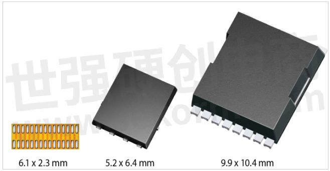
Figure 1. EPC2206 80V 2.2mohm GaNFET (on the left) compared to similar RDSON MOSFETs. Picture in scale.
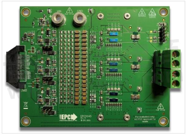
Figure 2. EPC9145 - 3 phase inverter power board based on EPC2206 – 10x12cm
EPC9145 is a motor drive evaluation board that features the EPC2206 and has everything needed except the microcontroller to drive a motor on the board. It can be operated with a maximum bus voltage of 70 VDC, and a maximum phase current of 25 ARMS. The motor controller can be chosen from those available on the market and can be connected using the proper EPC mate board. In Figure 2, from the left to the right there are the control connector, the signal conditioning circuit for voltages and currents feedback to the external microcontroller, the ceramic capacitor bank, three phase inverter with leg shunts and phase shunts and, finally, the motor connector.
dv/dt Switching Waveforms
The EPC9145 PCB has been laid out following the EPC optimal layout rules (Figure 4), that guarantee the lowest inductance in the power loop. The main criterion is to observe symmetry in the component placement, and to constrain the entire high frequency path in the top and first inner layer. In EPC9145 case, layout is slightly more complex because there are leg shunts in the high frequency power loop as shown in Figure 3.
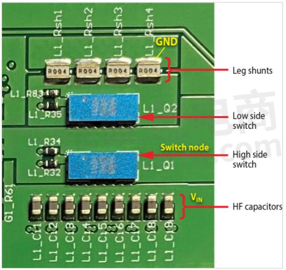
Figure 3. Detailed view of the switching cell

Figure 4. EPC optimal layout recommendation
The HF capacitors are nine 220nF size 0603, all in parallel, to reduce the overall inductance at high frequency. The same principle applies for the 1mΩ leg shunt sensor, which is made with four SMD resistors 4mΩ 0805 wide body. The result is visible in Figure 5 where the switching node of phase V swings over time in both rising and falling edges as shown.
The pictures in Figure 5 have been obtained with infinite persistence to capture all waveforms, so that the maximum dv/dt is clearly visible. No voltage overshoot has been observed and the dv/dt is clearly in range used in typical motor drive applications. The careful reader can observe that the dead time was set to 50ns (2.5 divisions).

Figure 5. Phase V rising edges at 30V bus / Phase V falling edges at 30V bus
Current Sensing In-Phase vs. Leg Shunts
When using discrete eGaN FETs or a GaN ePowerTM stage IC in an inverter for motor drive, it is common to use an in-phase current shunt together with an isolated (functionally or galvanically) IC that extracts the low voltage differential signal across the shunt resistor from the common mode of the switching phase. This approach has the advantage of giving the user continuous access to the phase current signal across the entire PWM period, except during switching events, where the signal may be influenced by the phases dv/ dt. However, when compared to leg shunt sensing, the higher cost and lower bandwidth of the in-phase shunt solution may be detrimental for GaN inverter adoption in motor drives.

Figure 6. In-phase and leg shunt current sensing comparison – NOTE: noise in the picture is picked up by nonoptimal measuring setup. Real signals are cleaner as it can be shown by controller current reconstruction.
The EPC9145 offers the user the chance to test both solutions and decide which fits best in his application. In fact, there are in-phase 1mΩ shunts as well as 1mΩ leg shunts per each switching cell. The 20x amplification gain, offset and polarity are the same for both circuits so that the user can connect either the one or the other sensing scheme to the external microcontroller without making any firmware change. As shown in Figure 5, the insertion of the shunt in the low side leg does not have detrimental effect on the switching behavior.

Figure 7a. Inner layer with shunt signal kelvin connections
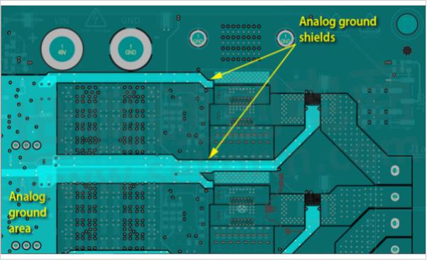
Figure 7b. Layers above and below with analog ground shielding of shunt kelvin traces
A comparison of the two current measuring methods, as well as the signal obtained from a current probe connected at the output of the inverter, is shown in Figure 6. When phase voltage is high, the signal across the leg shunt is null and the output of the amplifier is centered at 1.65V; when phase voltage is low, the current which is flowing in the in-phase shunt is also flowing in the leg shunt so the two amplified signals overlap. Conventional field-oriented control algorithms measure the current in the middle of the phase low voltage pulse (indicated by two stars in Figure 6), so, by simply changing the position of three jumpers on the EPC9145 board, it is possible to use any of the two signals.
Layout Rules for Accurate Current Sensing
The EPC9145 demonstrates the good practice in routing low voltage signals from the shunt resistors across the power board to the point where they are amplified and brought to the microcontroller connector. The main criterion is to perform kelvin measurement across the shunt and bring the traces as close as possible and shielded by analog ground cages on layers above and below the routing layer as shown in Figure 7. Another good practice is to divide digital and power ground from analog ground and connect them together in one single point far from the power loop paths.
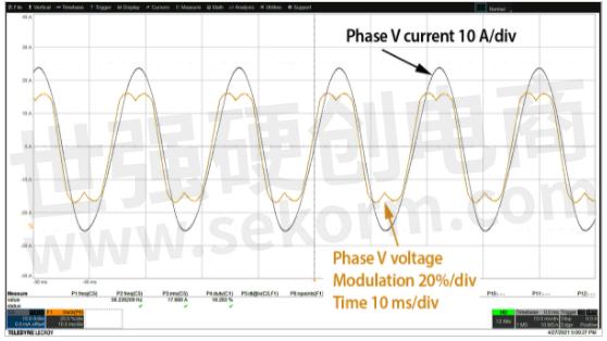
Figure 8. 40kHz 50ns DT operation, 60 VDC 17.5 ARMS phase current – leg shunt measure

Figure 9. Infrared picture (confirmed by a thermocoupler) at 60VDC 10ARMS phase current 40kHz 50ns DT
Operation Without Heatsink
Both in-phase and leg sensing were used when testing the EPC9145 in a motor bench setup with a hysteresis brake. Current and voltage waveforms at 17.5 ARMS 60VDC are shown in Figure 8. Figure 9 shows the temperature across the EPC2206 without heatsink and no air convection. In this case the current is 10 ARMS at 60VDC and the difference vs. ambient temperature is 30°C. Tests with heatsink with and without air convection are on-going and results will be reported soon in the board quick start guide.
The benefit of 100 kHz Operation
An eGaN-based inverter can be easily operated at 100kHz. The advantage is that the input voltage and current ripple decrease when the PWM frequency is increased, allowing the user to remove the electrolytic capacitors and use only ceramic that are smaller, lighter, and more reliable. The EPC9145 is populated on the top surface with ceramic capacitors and on bottom with electrolytic capacitors. There are placeholders on both top and bottom layers so the user can mount, or un-mount the capacitors and make their own trials and judgements to find the right operating point that optimizes weight, size, and thermal operation.
Conclusions
Many battery-powered motor applications are moving from conventional Si MOSFET, low PWM frequency to GaN Inverters that can run at higher PWM frequency and bring the advantage of reducing the size and the weight without sacrificing the overall system efficiency. With proper gate driving and optimal layout, the switching waveforms are clean and dv/dt is easily managed.
- |
- +1 赞 0
- 收藏
- 评论 0
本文由董慧转载自EPC,原文标题为:Utilizing GaN Inverters for Battery-Powered Motor Drive Applications,本站所有转载文章系出于传递更多信息之目的,且明确注明来源,不希望被转载的媒体或个人可与我们联系,我们将立即进行删除处理。
相关推荐

【应用】基于氮化镓器件构建数据中心的DC/DC转换器,有效提高效率、缩小尺寸并降低总体拥有成本
提高功率转换的效率是减少数据中心的能耗的主要方法,人工智能、5G和大数据的发展实现更智能化,但需要更高功率才可以为服务器、存储和网络机架供电。高效的氮化镓器件能够支持新的48 V机架设计、减少了云数据中心的能源费用、减少冷却要求和提高整体电力使用效率

【应用】氮化镓场效应晶体管和IC助力数据中心的AC/DC转换,实现比硅器件更高的功率和可靠性
云计算、可穿戴设备、机器学习、自动驾驶和物联网等应用的扩展实现了更加数据密集的世界、对数据中心的需求更大和功耗随之而增加。交流到直流的开关电源的效率、功率密度和成本非常重要,氮化镓器件应用可以有效提高功率密度和降低成本。

【应用】eGaN FET用于12~48V汽车DC-DC应用,具有比硅MOS更高的效率、更小的尺寸和成本
汽车电子产品现在可以充分利用增强型氮化镓(eGaN®)器件更高效率,速度,更小尺寸和更低成本的优势。目前已经出现了一些大型应用,其中GaN具有比老式硅MOSFET更明显的优势,特别是在48V输入节点上。本文中EPC就将详细地对两种产品进行对比,并推荐通过了AEC-Q101认证的eGaN FET—EPC2206。

EPC eGaN®FET/晶体管选型表
EPC提供增强型氮化镓半桥功率晶体管/增强型功率晶体管/功率晶体管的选型:配置:Dual Common Source、Dual with Sync Boot、Half Bridge、Half Bridge Driver IC、HS FET + Driver + Level Shift、Single、Single - AEC Q101、Single – Rad Hard、Single with Gate Diode、Single with Gate Diode – AEC-Q101、Dual Common Source - AEC Q101,VDS最大值(V):15~350V;VGS最大值(V):5.75~7V
|
产品型号
|
品类
|
Configuration
|
VDSmax(V)
|
VGSmax(V)
|
Max RDS(on) (mΩ)
@ 5 VGS
|
QG typ(nC)
|
QGS typ (nC)
|
QGD typ (nC)
|
QOSS typ (nC)
|
QRR(nC)
|
CISS (pF)
|
COSS (pF)
|
CRSS (pF)
|
ID(A)
|
Pulsed ID (A)
|
Max TJ (°C)
|
Package(mm)
|
Launch Date
|
|
EPC2040
|
Enhancement Mode Power Transistor
|
Single
|
15
|
6
|
30
|
0.745
|
0.23
|
0.14
|
0.42
|
0
|
86
|
67
|
20
|
3.4
|
28
|
150
|
BGA 0.85 x 1.2
|
Apr, 2017
|
选型表 - EPC 立即选型

基板供应商替代产品/工艺变更通知(PCN)(PCN240531)
描述- EPC宣布Wafer Works成为第二家合格的Si基板供应商,拥有IATF 16949认证。此变更不影响产品形式、尺寸或功能。EPC将在客户接受PCN后开始使用Wafer Works的基板生产设备。受影响的销售产品编号见附录I。
型号- EPC2212,EPC2214,EPC2216,EPC2014C,EPC2016C,EPC2030,EPC2032,EPC2031,EPC8010,EPC2069,EPC2024,EPC8009,EPC2001C,EPC2202,EPC2029,EPC2015C,EPC2206,EPC2007C,EPC8002,EPC2040,EPC2021,EPC2020,EPC2023,EPC2221,EPC2022,EPC7014,EPC8004,EPC2716C
基板供应商替代产品/工艺变更通知(PCN)(PCN240501)
描述- EPC宣布Wafer Works成为Si基板第二家批准供应商,拥有IATF 16949认证。此变更不影响产品形式、尺寸或功能。EPC将在客户接受PCN后开始使用Wafer Works的基板生产设备。受影响的销售部分编号见附录I。
型号- EPC2212,EPC2214,EPC2216,EPC2014C,EPC2016C,EPC2030,EPC2032,EPC2031,EPC8010,EPC2069,EPC2024,EPC8009,EPC2001C,EPC2202,EPC2029,EPC2015C,EPC2206,EPC2007C,EPC8002,EPC2040,EPC2021,EPC2020,EPC2023,EPC2221,EPC2022,EPC7014,EPC8004,EPC2716C

【方案】高动态高速TOF相机优选元器件方案
描述- 本方案通过采用Melexis公司汽车级的高动态高速TOF传感技术、EPC公司的eGaN工艺的高速、低RDS(on)晶体管及其相关器件,帮助TOF相机实现高动态高速测量,避免红爆现象并可在强日光下工作,同时帮助降低发热量,提升可靠性,产品应用更广泛。
型号- EPC2212,EPC2016,MLX75023,FC-12M,MLX75024,MLX75123,EPC2032,EPC2031,SGM41285,EFM32TG11,EFM32ZG,SG-8018,EPC2202,SGM6607,FA-20H,EPC2206,EPC2021,EPC2022,TSX-3225,SGM6232,PH,SGM220,SGM601X,FA-128,FC-135,RX8010SJ,EFM32HG,MGV

开发板EPC9147C快速入门指南
描述- 该资料介绍了EPC9147C电机驱动控制器接口板,该板可与STM32 NUCLEO-G431RB开发板配合使用,用于控制三相eGaN® FET/IC电机驱动逆变器。资料详细说明了板的连接方式、人机界面控制、测试点、监控跳线设置、兼容的电机驱动逆变器、电气规格、连接细节、编程方法和附加功能端口。此外,还提供了电机调试程序和ST Motor Control Workbench的详细使用说明。
型号- EPC9147C,0603YC104KAT2A,M50-203005,4-103185-0-02,EPC2206,LTST-C193KRKT-5A,STM32G431RBT6,EPC9145,EPC2152,ESQ-119-24-T-D,EPC9146,87227-4,RNCF0603BTE20K0,SBH11-PBPC-D17-ST-BK,STM32,M63P103KB30T607,RT0603BRD071KL,ERJ-3GEY0R00V,SFH11-PBPC-D17-ST-BK,8834

氮化镓可靠性和寿命预测:第16阶段可靠性报告
型号- EPC2212,EPC2069,EPC2302,EPC2203,EPC2034C,EPC2202,EPC2204,EPC2215,EPC2014C,EPC2218,EPC2207,EPC2206,EPC2071,EPC2052,EPC2051,EPC2045,EPC21701,EPC21601

A Brief History of Power Transistors for Engineers
In this article, we reflect on the history of semiconductors from the early days of bipolar transistors to the present advancements and promise of gallium nitride (GaN) FETs and ICs.

The 150V, 3mΩ EPC2305 and the 200V, 5mΩ EPC2304 GaN FETs offering higher performance and smaller solution size
EPC introduces the 150 V, 3 mΩ EPC2305 and the 200 V, 5 mΩ EPC2304 GaN FETs offering higher performance and smaller solution size and cost for DC-DC conversion, AC/DC SMPS and chargers, solar optimizers and microinverters, and motor drives.


EPC氮化镓晶体管选型表
EPC提供以下氮化镓功率晶体管/GaN功率晶体管选型,最大耐压15V-350V,持续电流0.5A-90A,导通阻抗1.45Ω-3300mΩ,导通电荷0.044nC-19nC,峰值电流0.5A-590A。
|
产品型号
|
品类
|
最大耐压(V)
|
持续电流(A)
|
导通阻抗(mΩ)
|
导通电荷(nC)
|
峰值电流(A)
|
封装(mm)
|
|
EPC2040
|
Enhancement Mode Power Transistor
|
15V
|
3.4A
|
30mΩ
|
0.745nC
|
28A
|
BGA 0.85 mm*1.2mm
|
选型表 - EPC 立即选型

电子商城

授权代理品牌:集成电路


授权代理品牌:分立元件


授权代理品牌:接插件及结构件


授权代理品牌:部件、组件及配件


授权代理品牌:电源及模块


授权代理品牌:电子材料


授权代理品牌:仪器仪表及测试配组件


授权代理品牌:电工工具及材料


授权代理品牌:机械电子元件


授权代理品牌:加工与定制


登录 | 立即注册
提交评论